Repeatable timing error correction system for use in a servo writer

Inactive Publication Date: 2007-04-03
WESERN DIGITAL TECH
View PDF11 Cites 32 Cited by
  • Summary
  • Abstract
  • Description
  • Claims
  • Application Information

AI Technical Summary

Benefits of technology

[0017]In one embodiment, the servo writer may operate in an in-situ environment in which the servo writer is directly coupled to a disk drive comprising a head disk assembly (HDA) including a disk or several disks, an actuator arm, and a head coupled to the distal end of the actuator arm. The servo writer may control the HDA such that the actuator arm is rotated to position the head radially over the disk in order to write servo sectors onto the disk based on an output clock

Problems solved by technology

Unfortunately, conventional clocking systems utilized in servo writers often impart repeatable timing errors into the servo writing process such that servo sectors (e.g. 20–2N) are written to the disk in a manner that incorporates the repeatable timing errors of the clocking system.
This results in poor accuracy in the location of the servo sectors written onto the disk, which can result in poor tracking behavior of the disk drive servo system, and a lower data capacity than may otherwise be achieved.
Eccentricity associated with the servo sectors results in timing uncertainties being introduced into the servo control

Method used


Image

  • Repeatable timing error correction system for use in a servo writer
  • Repeatable timing error correction system for use in a servo writer
  • Repeatable timing error correction system for use in a servo writer

Examples


Example

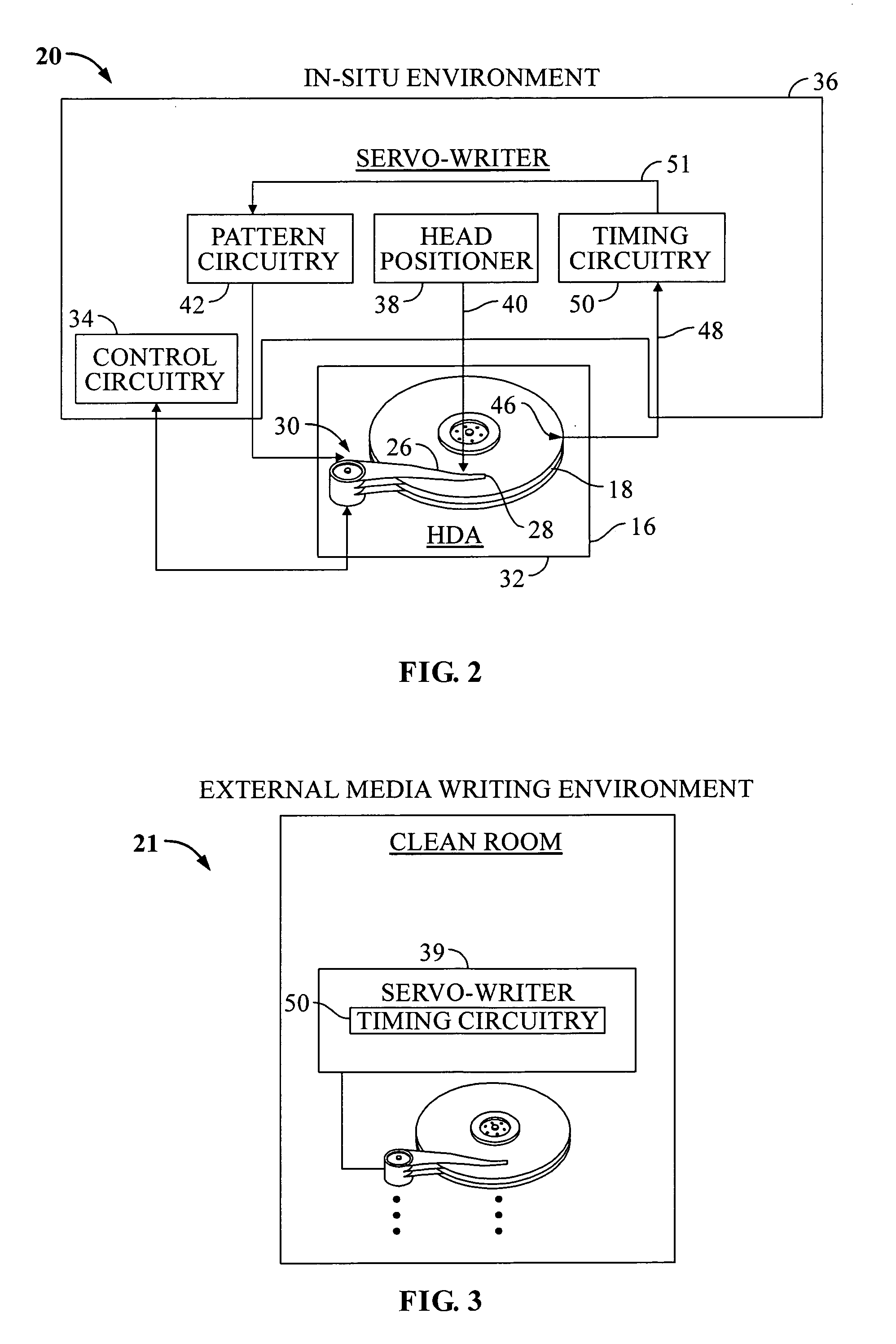
[0030]Looking at FIGS. 2 and 3, examples of servo writers for writing servo sectors onto a disk responsive to a reference digital clock signal and for compensating for repeatable timing errors associated with the reference digital clock signal are illustrated. Particularly, timing circuitry, according to embodiments of the invention, is shown in each of the exemplary servo writers, the components of which will be discussed in more detail later. The timing circuitry 50, as will be discussed, is utilized for compensating for repeatable timing errors associated with a reference digital clock signal.

[0031]Particularly, FIG. 2 is an example of a servo writer in an in-situ environment, in which embodiments of the invention for the timing circuitry 50 may be utilized. As shown in FIG. 2, a servo writer 36 operates an in-situ environment 20, in which the servo writer 36 writes servo sectors (previously discussed) and other servo information to a disk 18 of a disk drive 16.

[0032]The disk dri...


PUM


Abstract

A servo writing system for writing servo sectors onto a disk includes a direct digital synthesizer (DDS) that forms a phase and frequency adjustable continuous wave signal based upon a reference digital clock signal. A PLL coupled to the DDS measures repeatable timing errors (RTEs) associated with the continuous wave signal and generates an output clock signal that is used to clock the writing of servo sectors onto the disk. A digital control system is coupled to the DDS and the PLL, which calculates repeatable error compensation adjustment values based on the RTEs measured using the PLL. The compensation adjustment values may be applied to the DDS such that the DDS compensates for the RTEs and such that the output clock signal used to clock the writing of the servo sectors onto the disk includes minimal RTEs.

Description

BACKGROUND OF THE INVENTION[0001]1. Field of the Invention[0002]The present invention relates to repeatable timing error correction systems and methods. More particularly, the present invention relates to repeatable timing error correction systems and methods for use with a servo writer.[0003]2. Description of the Prior Art and Related Information[0004]Computer systems often rely on disk drives for storing and retrieving data. Disk drives typically employ a moveable head actuator to frequently access large amounts of data stored on a disk. One example of a disk drive is a hard disk drive. A conventional hard disk drive has a head disk assembly (“HDA”) including at least one magnetic disk (“disk”), a spindle motor for rapidly rotating the disk, and a head stack assembly (“HSA”) that includes a head gimbal assembly (HGA) with a moveable transducer head for reading and writing data. The HSA forms part of a servo control system that positions the moveable transducer head over a particul...

Claims


Application Information

Patent Timeline
IPC IPC(8): G11B5/09
CPCG11B5/59627
Inventor BRYANT, LAWRENCE M.
Owner WESERN DIGITAL TECH
Why Eureka
Try Eureka