
Diagnostic system for an appliance

a technology for diagnosing systems and appliances, applied in the direction of electric controllers, instruments, ignition automatic control, etc., can solve the problems of increasing the cost of preparing meals, increasing the cost of additional benefits, and no longer the norm for family members to be home all day, so as to achieve accurate replacement

Active Publication Date: 2007-04-03
MAYTAG
View PDF24 Cites 59 Cited by
  • Summary
  • Abstract
  • Description
  • Claims
  • Application Information

AI Technical Summary

Benefits of technology

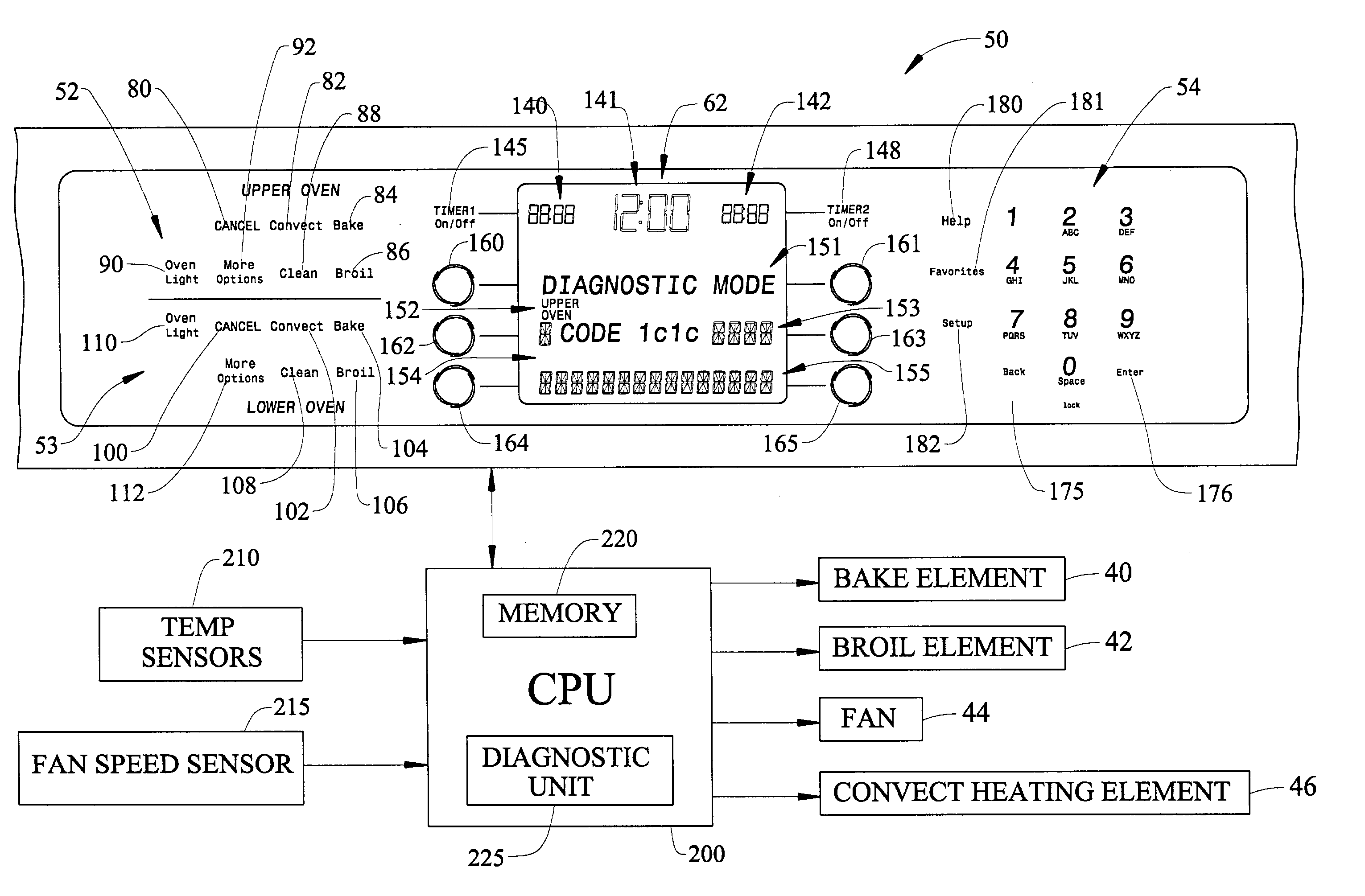
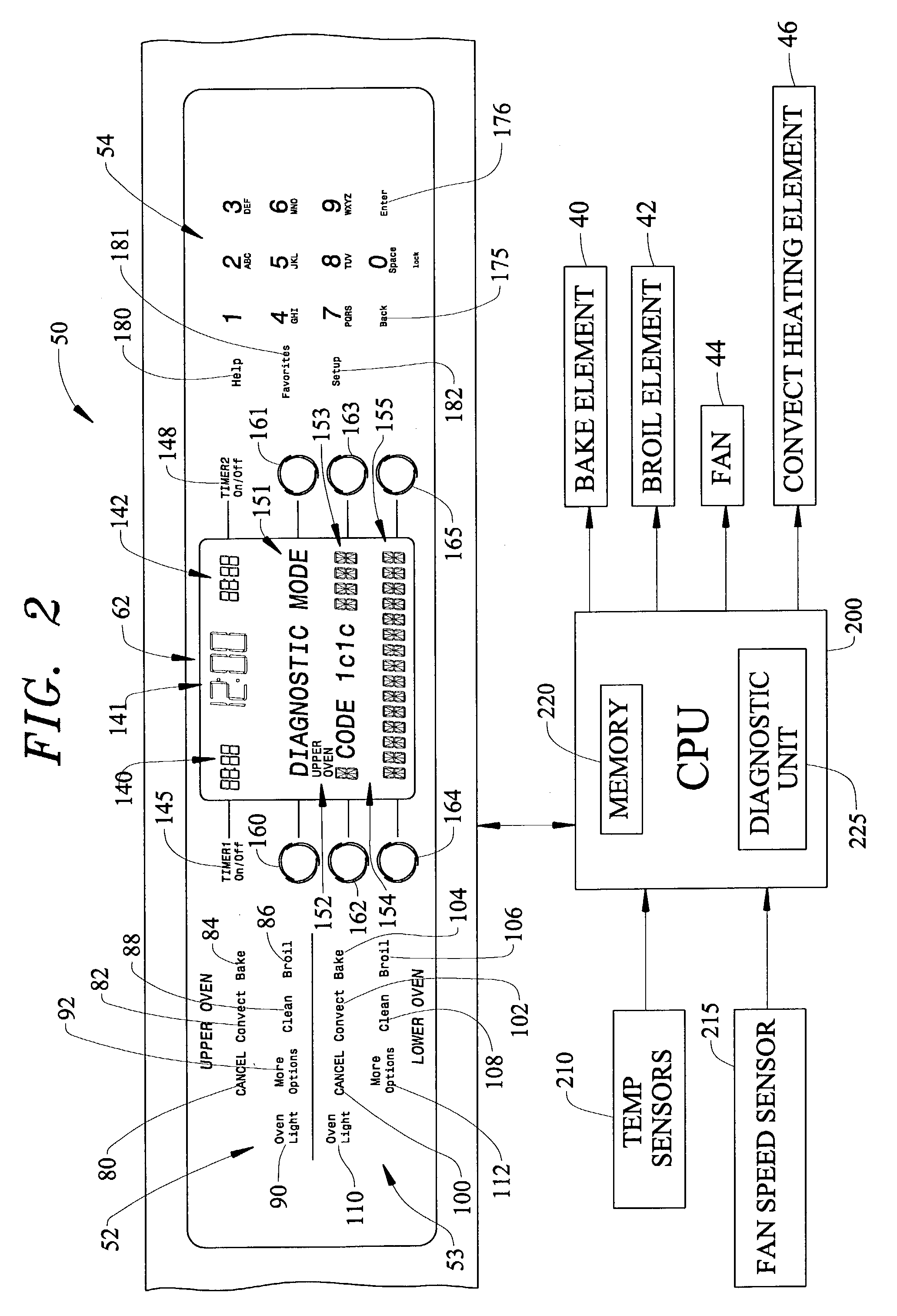
[0007]The present invention is directed to a system and method of evaluating and displaying a failure in an electronic appliance control system through the use of fault codes. In accordance with a preferred embodiment of the invention, diagnostic codes are provided which indicate both the primary system where a fault occurs and the subsystem in fault. The diagnostic codes are displayed so that repair personnel may be able to more accurately replace only the faulty part, as opposed to replacing an entire appliance control system.

Problems solved by technology

For instance, in the art of cooking appliances, it is no longer the norm to have a family member home all day with time to cook and prepare meals.
The luxury of spending time in preparing a meal is becoming less and less affordable.
Of course, these additional benefits add considerably to the expense of the control system and its replacement cost.
Correspondingly, this advanced technology has significantly added to the manufacturer's warranty expenses.
All too often, a completely functional control is completely replaced because of a failure of only a sub-system, such as a sensor and the like, that is connected to the electronic control.
Obviously, this can represent a cost to the manufacturer which must be controlled.

Method used


Image

  • Diagnostic system for an appliance
  • Diagnostic system for an appliance
  • Diagnostic system for an appliance

Examples


Embodiment Construction

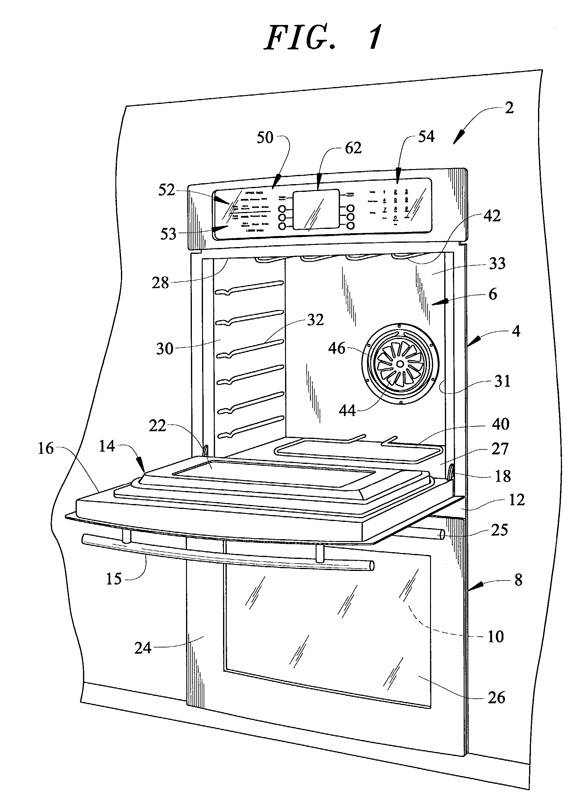
[0013]With initial reference to FIG. 1, a cooking appliance constructed in accordance with the present invention is generally indicated at 2. Cooking appliance 2, as depicted, constitutes a double wall oven. However, it should be understood that the present invention is not limited to this or other types of cooking appliances, but rather can be incorporated into various types of domestic appliances, e.g., clothes washing machines, clothes dryers, dishwashers, refrigerators and the like. In any event, in the embodiment shown, cooking appliance 2 constitutes a dual oven wall unit including an upper oven 4 having upper oven cavity 6 and a lower oven 8 having a lower oven cavity 10. Cooking appliance 2 includes an outer frame 12 for supporting both upper and lower oven cavities 6 and 10.

[0014]In a manner known in the art, a door assembly 14 is provided to selectively provide access to upper oven cavity 6. As shown, door assembly 14 includes a handle 15 at an upper portion 16 thereof. Do...


PUM


Abstract

A system and method of determining and displaying a failure in an electronic appliance control system employs diagnostic codes which indicate both a primary system where a fault occurs and a subsystem in fault. The diagnostic codes are displayed so that repair personnel may be able to more accurately replace only the faulty part, as opposed to replacing an entire appliance control system. The diagnostic codes are established to include a plurality of digits represented by a combination of letters and numbers. The electronic appliance control also preferably records a specific series of diagnostic steps taken to verify replacement of only an actual faulty component.

Description

BACKGROUND OF THE INVENTION[0001]1. Field of the Invention[0002]The present invention pertains to the art of appliances and, more particularly, to a system for diagnosing a fault or failure in a domestic, electronic appliance.[0003]2. Discussion of the Prior Art[0004]In recent years, domestic appliances have been undergoing substantial changes and other advancements. For instance, in the art of cooking appliances, it is no longer the norm to have a family member home all day with time to cook and prepare meals. Today, more and more consumers must rush home from work to prepare meals for themselves or for their families. In today's fast paced society, time is of the essence. The luxury of spending time in preparing a meal is becoming less and less affordable. As such, consumers demand an oven that will cook a meal in less time than conventional ovens, without sacrificing the quality of the prepared food. In order to meet these demands, manufacturers are combining conventional radiant...

Claims


Application Information

Patent Timeline
Patent Type & Authority Patents(United States)
IPC IPC(8): G05B15/00G06F11/00G05B23/02
CPCG05B23/0272G05B23/0283
Inventor BOYER, MARK A.KENDALL, TONY E.LARD, BRIAN A.STRICKLAND, JEFFREY C.
Owner MAYTAG
Learn More