Wire harness design supporting method and program

a technology of supporting method and wire harness, applied in the direction of analogue processes for specific applications, instruments, electric/magnetic computing, etc., can solve the problems of long time and enormous manpower, and achieve the effect of facilitating the transformation of three-dimensional data

Inactive Publication Date: 2007-04-03
SUMITOMO WIRING SYST LTD
View PDF14 Cites 26 Cited by
  • Summary
  • Abstract
  • Description
  • Claims
  • Application Information

AI Technical Summary

Benefits of technology

[0009]An object of the present invention is, therefore, to provide a wire harness design supporting method capable of easil

Problems solved by technology

However, in reality, at the time of manually creating a drawing of wire harnesses two-dimensionally developed, the development and designing has to be made by always considering twist, bending

Method used


Image

  • Wire harness design supporting method and program
  • Wire harness design supporting method and program
  • Wire harness design supporting method and program

Examples


Embodiment Construction

Description of Terms

[0058]Terms used in the specification will be described before describing a wire harness design supporting method according to the present invention.

[0059]“Path” in the specification denotes the shape of a path of a wire harness attached to a vehicle.

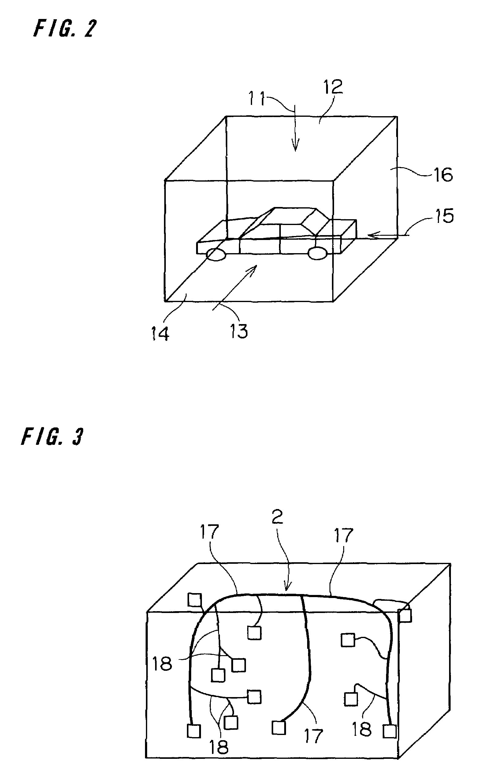
[0060]“Measurement point” denotes a point at which a wire harness is fixed or constrained by various electrical parts in a path of the wire harness and which is a point as a reference of dimension of the wire harness.

[0061]“Branch line” denotes a path from an end portion to be connected to a terminal on the other side to the first measurement point.

[0062]“Trunk line” denotes a main path excluding a branch line. The “trunk line” is further divided into a “reference trunk line” and a “branch line”.

[0063]The “reference trunk line” denotes a path portion as a center of the path.

[0064]The “branch line” denotes a trunk line branched from the reference trunk line.

[0065]“Branching” denotes here that a wire harness is branche...


PUM


Abstract

To easily transform three-dimensional data of a wire harness into a two-dimensional drawing. Wire harness data of a wire harness to be routed in a desired object is inputted to a computer. The wire harness data includes coordinate information which is three-dimensionally designed in a state adapted to the object of routing. A development plane for two-dimensionally developing the wire harness data is set. The wire harness data is divided into a plurality of segments S1 to S5 at predetermined division points, and is sequentially developed to the development plane on the segment unit basis from a start point P1 of a reference trunk line 17 via a branch line 18 to a termination point, thereby two-dimensionally developing the wire harness data on the segment unit basis so that all of the segments S1 to S5 are included in the development plane.

Description

BACKGROUND OF THE INVENTION[0001]1. Field of the Invention[0002]The present invention relates to a wire harness design supporting method and a technique related to the method.[0003]2. Description of the Background Art[0004]Generally, a wire harness installed on a vehicle is designed in such a manner that layout of main parts such as an engine, a radiator, an air conditioner and a car stereo, and various electrical components such as a control unit for controlling the main parts is designed, and after that, as shown in FIG. 21, while checking interference with the various electrical components and the vehicle body shape by using a software program called a three-dimensional design system (three-dimensional CAD) on a computer, routing of wire harnesses is designed through the various electrical components and the vehicle body so as to electrically connect predetermined electrical components. In FIG. 21, reference numeral 1 denotes a three-dimensional model indicative of the body of a ...

Claims


Application Information

Patent Timeline
IPC IPC(8): G06G7/48B60R16/02G06F17/50H01B13/012H02G3/38
CPCB60R16/0207G06F17/509G06F17/5095G06F2217/36G06F30/15G06F30/18G06F2113/16
Inventor OZAKI, SATORU
Owner SUMITOMO WIRING SYST LTD
Why Eureka
Try Eureka