Adjustable-length compression spring

a compression spring and adjustable technology, applied in the field of adjustable length compression springs, can solve the problems of inferior dimensional requirements of the compression spring with the control head screwed, and achieve the effect of greater solidity

Inactive Publication Date: 2007-04-10
SUSPA
View PDF19 Cites 3 Cited by
  • Summary
  • Abstract
  • Description
  • Claims
  • Application Information

AI Technical Summary

Benefits of technology

[0007]The gist of the invention resides in integrating the locking mechanism into the piston rod of the compression spring within the casing. As a result, the compression spring cooperates with the locking mechanism that serves for implementation of arrest, forming a compact constructional unit. The dimensional requirements of this unit are inferior to those of a compression spring with a control head screwed on. Moreover, the locking elements of the mechanism are excellently protected inside the casing of the compression spring so that they can be made comparatively small. Faulty assembly conditioned by erroneous allocation of a control head to the compression spring, and thus faulty adaptation of the lift of stroke of the locking mechanism in relation to the release lift of stroke of the compression spring are avoided just as well. The locking mechanism according to the invention is able to provide for sufficient lift of stroke so that it may be used even in compression springs that have a comparatively important stroke of release.
[0008]A locking mechanism can be manufactured for solidity at a low cost when it is characterized by a snap-in guide element, stationary in the casing, for guidance of a first of the locking elements in the direction of displacement of the valve pin, the locking elements cooperating with the snap-in guide element such that change-over between the two locking positions is obtained by rotation, regularly in the same sense of rotation, of the second locking element, which is not longitudinally guided by the snap-in guide element, in relation to the first locking element, which is longitudinally guided; and such that the locking positions are obtained by locking cooperation of the second locking element with the snap-in guide element. Similar locking mechanisms having made a good account of themselves in retractable-ballpoint-pen mechanisms.
[0011]In keeping with a preferred embodiment, the longitudinally guided locking element has inclined delivery wall sections, along which the second locking element slides upon displacement from the position of release into the position of blocking and from the position of blocking into the position of release, one and the same delivery wall section of the longitudinally guided locking element being used for displacement from the position of release into the position of blocking as well as for displacement from the position of blocking into the position of release. With a certain section of a wall of delivery of the longitudinally guided locking element having several jobs upon change-over of the locking mechanism, the longitudinally guided locking element can be embodied for greater solidity in the vicinity of the delivery-wall sections as compared to alternatives in which several wall sections fulfil the jobs of delivery from the position of release into the position of blocking on the one hand and from the position of blocking into the position of release on the other.
[0012]With the longitudinally guided locking element comprising an intermediate stop for defined motion of rotation of the second locking element such that, prior to the second locking element cooperating with the snap-in guide element for locking engagement, the longitudinally guided locking element disengages from catching recess of the second locking element, by way of which the second locking element cooperates with the snap-in guide element for locking engagement, this will help prevent the locking mechanism from getting stuck.

Problems solved by technology

The dimensional requirements of this unit are inferior to those of a compression spring with a control head screwed on.

Method used


Image

  • Adjustable-length compression spring
  • Adjustable-length compression spring
  • Adjustable-length compression spring

Examples


Embodiment Construction

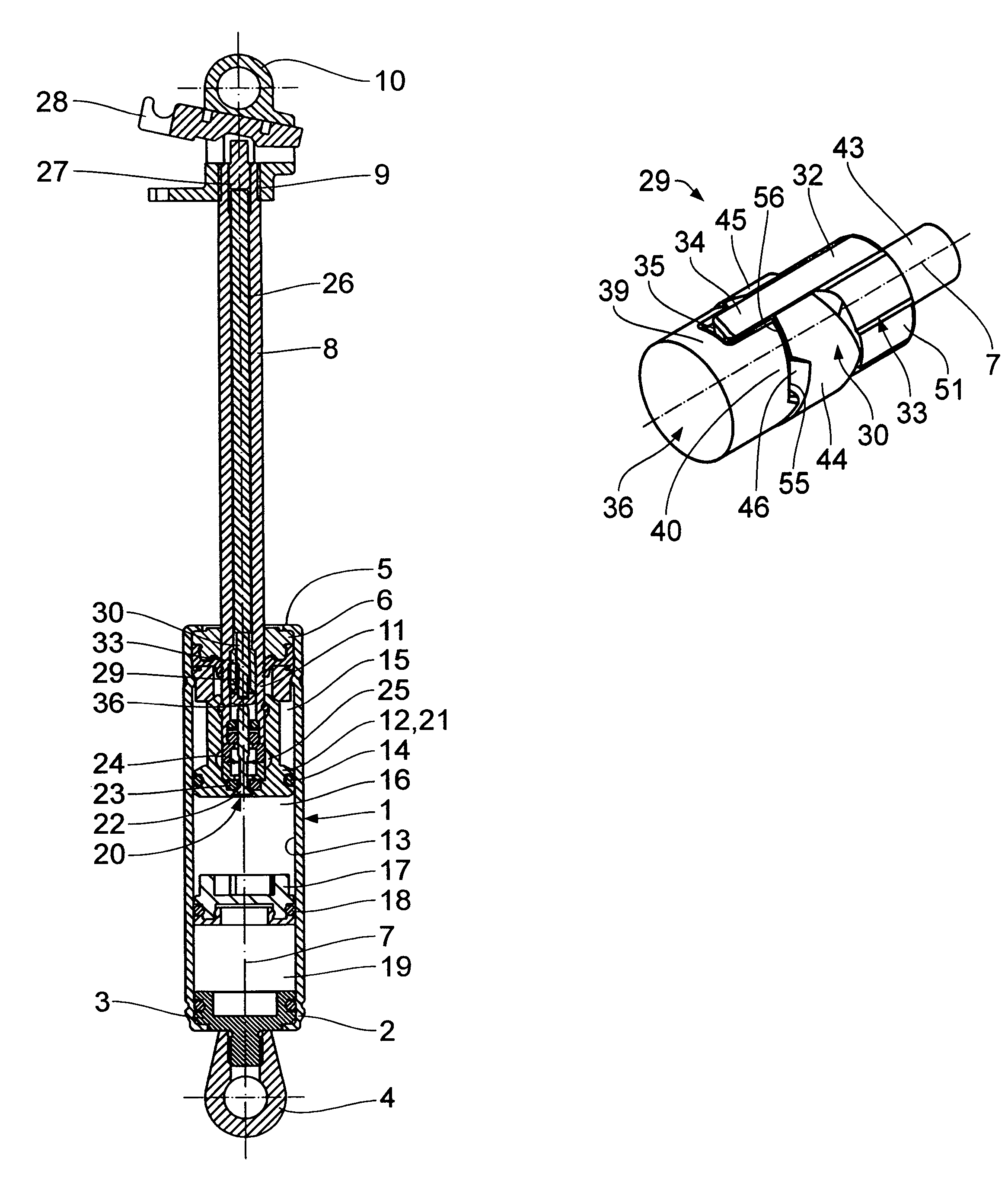
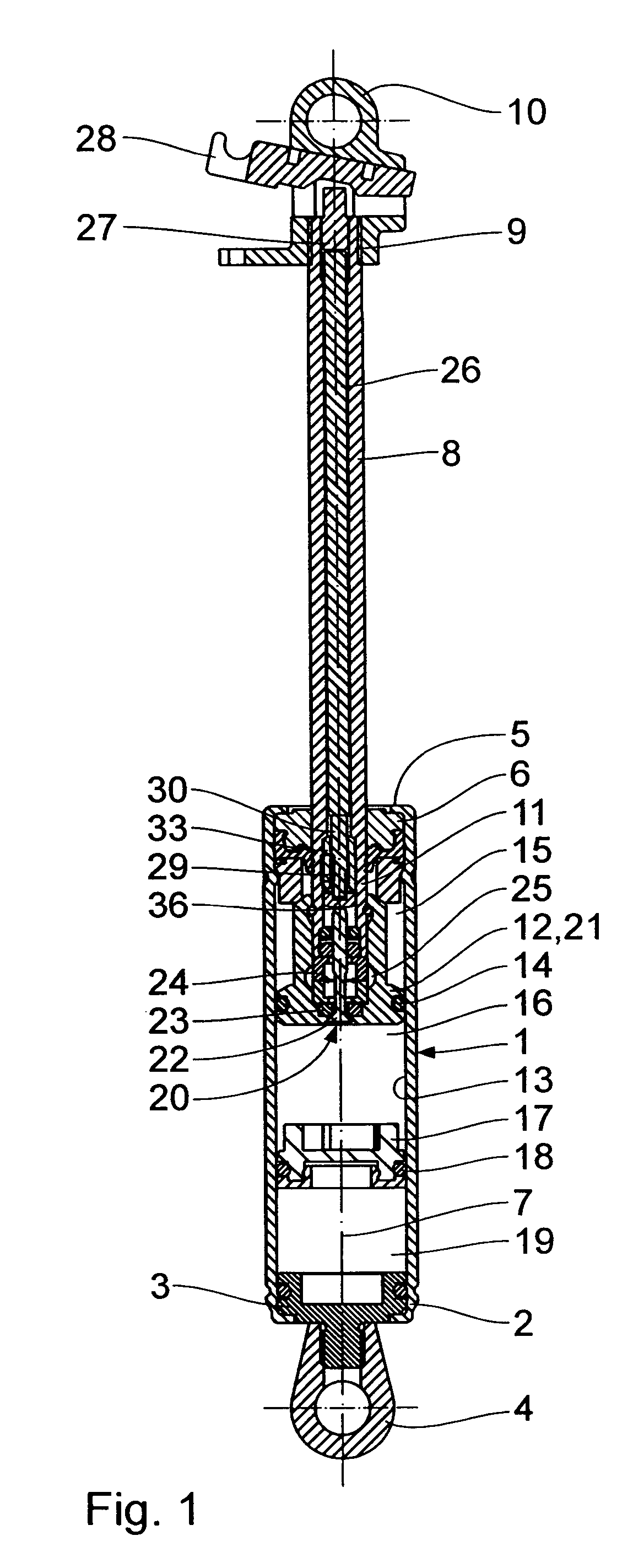
[0018]The blockable, adjustable-length compression gas spring seen in FIG. 1 includes a substantially cylindrical casing 1 made from a tube, one end 2 of which is closed gas-tightly by a bottom 3 which a fastening element 4 is attached to. The other end 5 of the casing 1 is provided with an annular guide and seal unit 6 for liquid sealing, the unit 6 serving to guide and seal a piston rod 8 that is displaceable in the casing 1 concentrically of the central longitudinal axis 7 thereof. The free end 9, outside the casing 1, of the piston rod 8 is likewise provided with a fastening element 10.

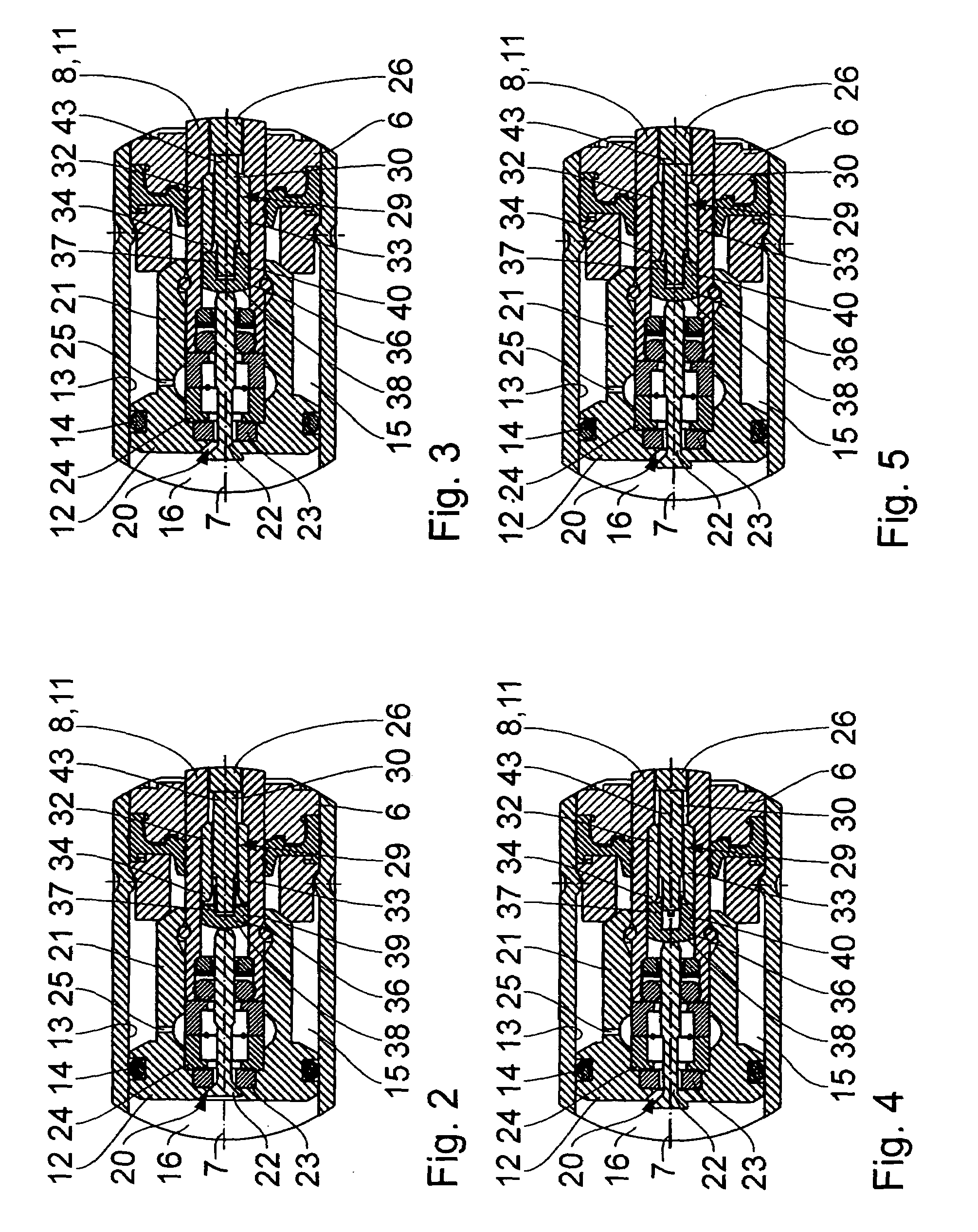
[0019]The end 11, inside the casing 1, of the piston rod 8 is provided with a piston 12 which is guided on an inside wall 13 of the casing 1 and liquid-sealed towards the casing 1 by a seal 14. The piston 12 divides the inside of the casing 1 into a first sectional casing chamber 15 between the piston 12 and the guide and seal unit 6 and a second sectional casing chamber 16 that faces away from th...


PUM


Abstract

An adjustable-length compression spring comprises a casing filled with pressure fluid. A piston rod is sealingly extended through a guide and seal unit which closes the casing, a piston, which is sealingly guided therein, being joined to the piston rod. The piston divides the casing into two sectional casing chambers, which are filled with pressure fluid. For connection to each other of the sectional casing chambers, provision is made for a valve operated by a valve pin. The casing includes a locking mechanism which comprises a first and a second locking element, the first of which being in pushing connection with a first operating element and the second with the valve pin. They cooperate in the way of a retractable-ballpoint-pen mechanism so that, in a first position of locking, the valve pin takes a position of release with free connection between the sectional casing chambers and, in a second position of locking, it takes a position of blocking with any connection between the sectional casing chambers being shut off. This type of integrated locking mechanism can be made solid, nevertheless needing little space.

Description

BACKGROUND OF THE INVENTION[0001]1. Field of the Invention[0002]The invention relates to an adjustable-length compression spring having a casing filled with pressure fluid; a guide and seal unit which closes the casing at a first end; a piston rod which, through the guide and seal unit, is extended from, and sealed towards, the first end and has an outer end; a piston which is joined to the piston rod and sealingly guided in the casing; a first sectional casing chamber which is unilaterally defined by the piston and filled with pressure fluid; a second sectional casing chamber which is connectable to the first sectional casing chamber and filled with pressure fluid; an operating valve for connection to each other of the sectional casing chambers, the valve comprising a valve pin to be actuated from outside the casing by an operating element, the valve pin being displaceable between a position of release and a position of blocking such that in the position of release of the valve pin...

Claims


Application Information

Patent Timeline
Patent Type & Authority Patents(United States)
IPC IPC(8): F16F9/32F16F9/34A47B9/10A47C3/30F16F9/02F16F9/10F16F9/46
CPCF16F9/0245F16F9/461F16F9/10A47C3/30A47B9/10
Inventor KNAUST, HOLGER
Owner SUSPA
Why Eureka
Try Eureka