Lighting device for a vehicle and method for controlling light distribution of the lighting device

Inactive Publication Date: 2007-04-10
DENSO CORP
View PDF19 Cites 12 Cited by
  • Summary
  • Abstract
  • Description
  • Claims
  • Application Information

AI Technical Summary

Benefits of technology

[0008]The present invention therefore has an objective to provide a lighting device that provides flexibility in altering light distri

Problems solved by technology

Furthermore, the lighting devices are very small in size and thin in comparison with incandescent lamps and hal

Method used


Image

  • Lighting device for a vehicle and method for controlling light distribution of the lighting device
  • Lighting device for a vehicle and method for controlling light distribution of the lighting device
  • Lighting device for a vehicle and method for controlling light distribution of the lighting device

Examples


Embodiment Construction

[0038]The preferred embodiment of the present invention will be explained with reference to the accompanying drawings.

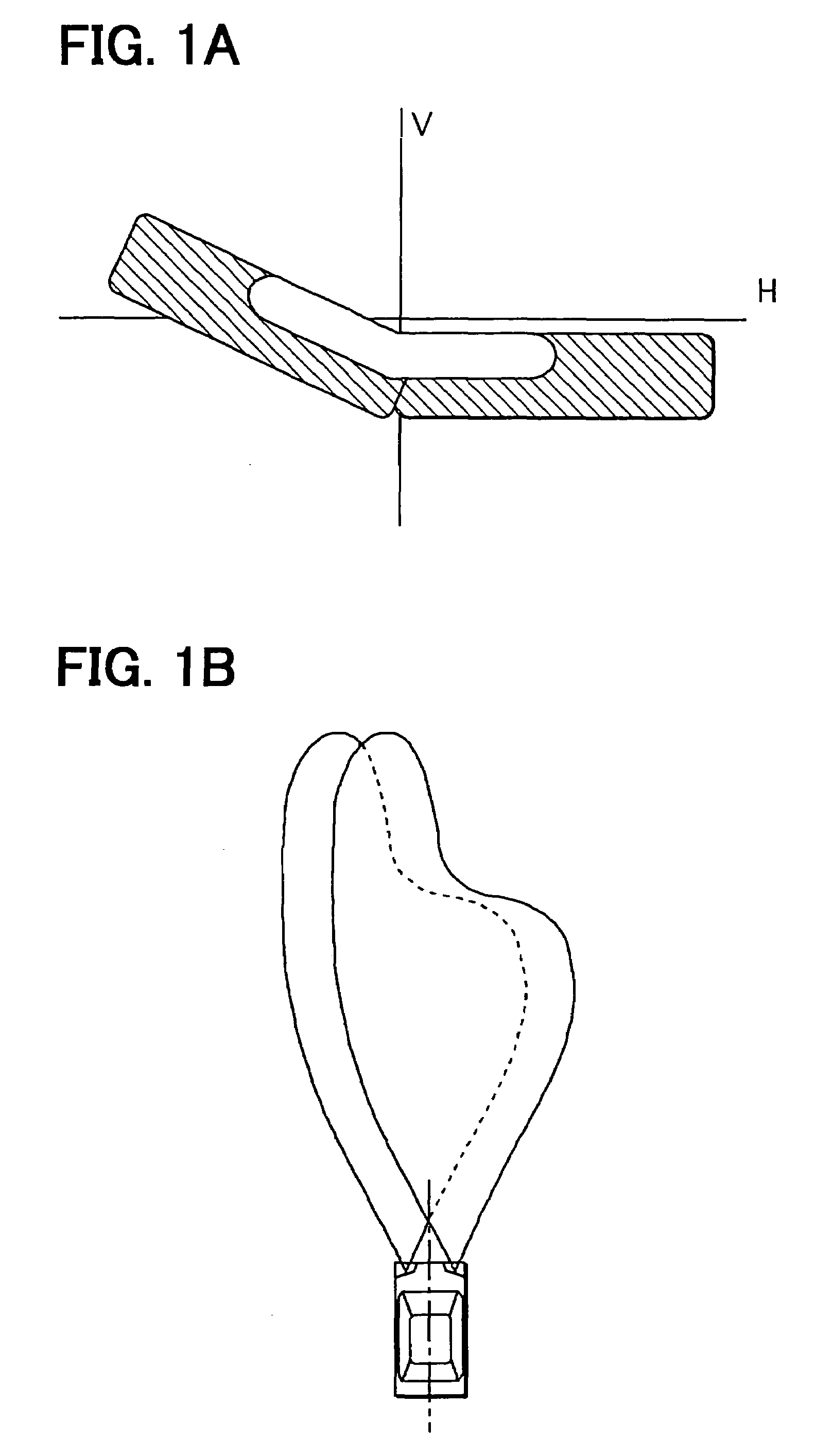
[0039]Headlights for a vehicle are required to have low-beam (dimmer-beam) light distribution areas shown in FIGS. 1A and 1B under the left-hand driving regulations. Higher intensity is required in the white area shown in FIG. 1A compared with the rest of area.

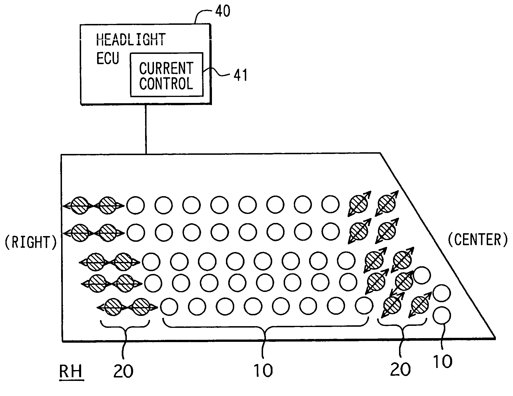
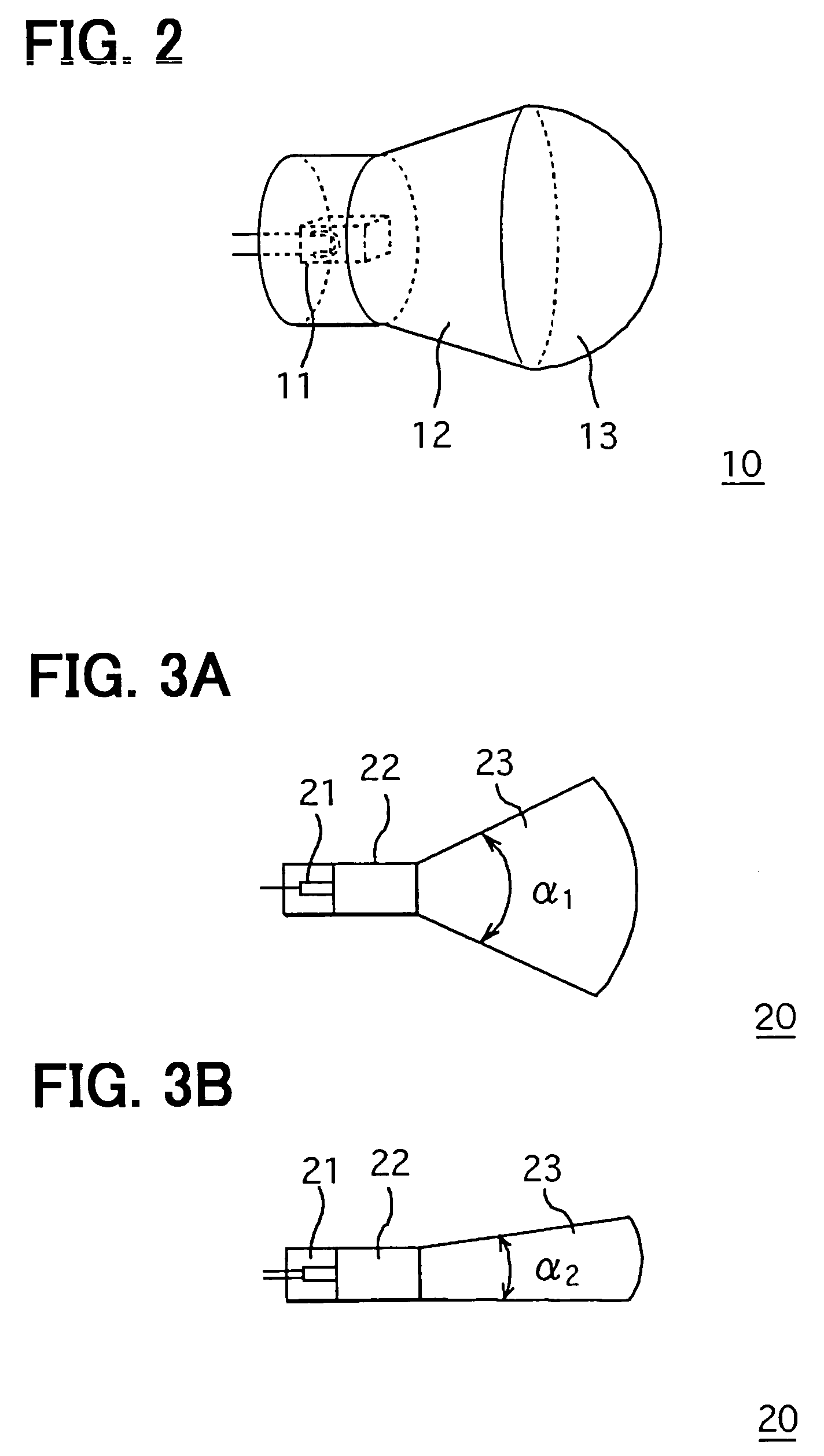
[0040]Each headlight includes convex light emitting devices 10 (first light emitting devices) shown in FIG. 2 and fan-shaped light emitting device 20 (second light emitting devices) shown in FIG. 3. Each convex device 10 is constructed of a white light emitting diode (LED) 11, a guiding member 12, and a convex light guide lens 13. The white LED 11 is provided as a first LED for lighting a narrow area. The convex light guide lens 13 having a paraboloidal surface is provided as a first light guide lens for passing light from the white LED 11 to outside in the form of a parallel pencil of light. The guiding member...


PUM


Abstract

A lighting device for a vehicle includes multiple light emitting devices. Each light emitting device is constructed of a light emitting diode as a light source and a light guide lens for guiding light emitted from the light emitting diode. The light emitting devices are formed in convex light emitting devices and fan-shaped light emitting devices. The convex devices and the fan-shaped devices have different light distribution characteristics. Therefore, light distribution areas and intensity of the lighting device are more flexibly adjusted than other lighting devices using light emitting diodes as light source.

Description

CROSS REFERENCE TO RELATED APPLICATION[0001]This application is based on and incorporates herein by reference Japanese Patent Application No. 2002-230514 filed on Aug. 7, 2002.FIELD OF THE INVENTION[0002]The present invention relates to a lighting device for a vehicle and a method for controlling a light distribution of the lighting device.BACKGROUND OF THE INVENTION[0003]A lighting device for a vehicle is used in different applications including head lamps, fog lamps, tale lamps, break lamps, and turn signal lamps. The vehicle includes passenger vehicles, motorcycles, bicycles, construction vehicles, and aircrafts. The lighting device has a light source, such as an incandescent lamp and a halogen lamp, a reflector, and a lens to obtain desired characteristics of the light distribution.[0004]The incandescent lamp and the halogen lamp are not efficient in converting electricity to light. Thus, a large amount of electricity is required to produce light of desirable intensity. This may...

Claims


Application Information

Patent Timeline
IPC IPC(8): B60Q1/00B60Q1/08B60Q1/10B60Q1/26F21K99/00F21S8/10F21S8/12F21V5/00F21V8/00F21W101/10F21W101/12F21W101/14F21Y101/02
CPCB60Q1/085F21S48/1747F21S48/1154F21S48/1233F21S48/1241F21S48/1291B60Q2300/054B60Q2300/112B60Q2300/114B60Q2300/122B60Q2300/132B60Q2300/312F21K99/00B60Q2300/21F21Y2115/10F21S41/143F21S41/28F21S41/24F21S41/27F21S41/663F21S45/60F21W2107/00F21S41/153
Inventor CHIGUSA, YUJIOKUMURA, KAZUHISA
Owner DENSO CORP
Why Eureka
Try Eureka