
Drive unit for vehicle

a technology for driving units and vehicles, applied in the direction of jet propulsion mounting, transportation and packaging, gearing, etc., can solve the problems of increasing costs and weight, and achieve the effect of increasing costs and heavy weigh

Inactive Publication Date: 2007-04-10
AISIN AW CO LTD +1
View PDF9 Cites 32 Cited by
  • Summary
  • Abstract
  • Description
  • Claims
  • Application Information

AI Technical Summary

Problems solved by technology

However, there are the problems in such a system.
As its result, these parts are large-sized and heavy in weight in comparison with the same kind of parts for an automatic transmission (A / T) so that there is a concern with increased cost.

Method used


Image

  • Drive unit for vehicle
  • Drive unit for vehicle
  • Drive unit for vehicle

Examples


Embodiment Construction

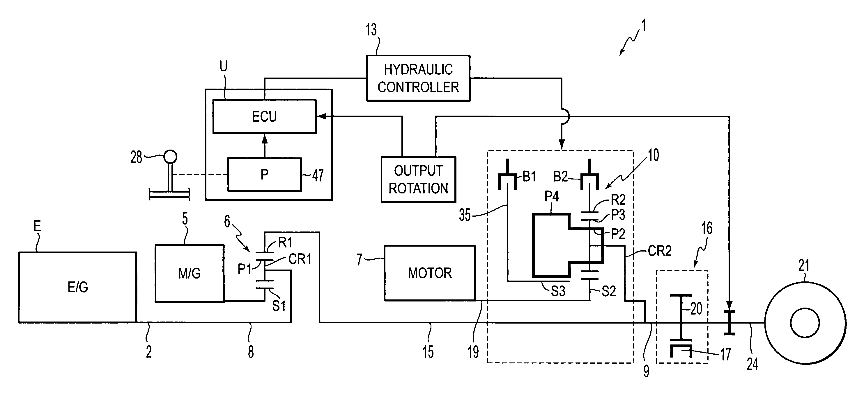
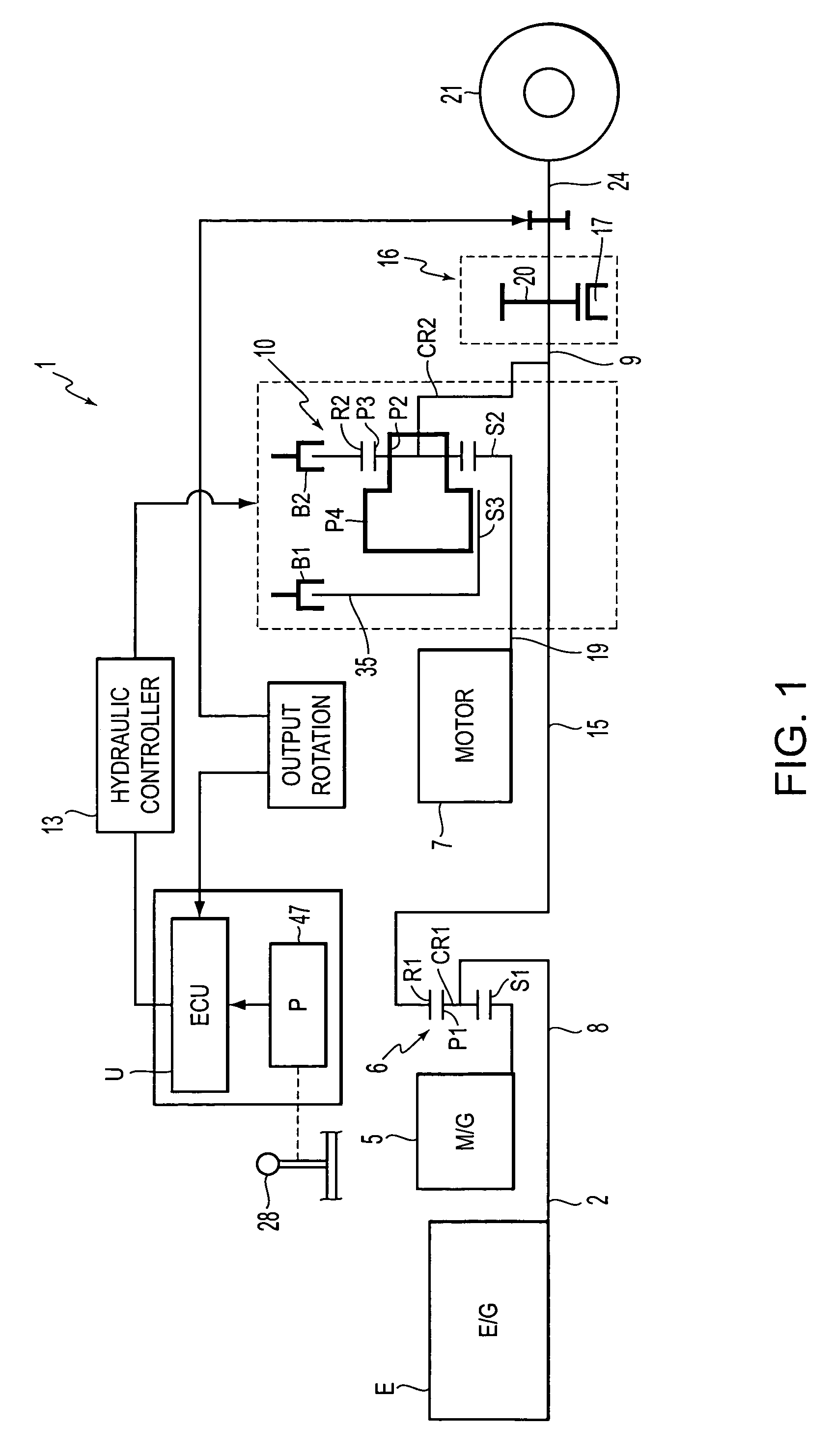
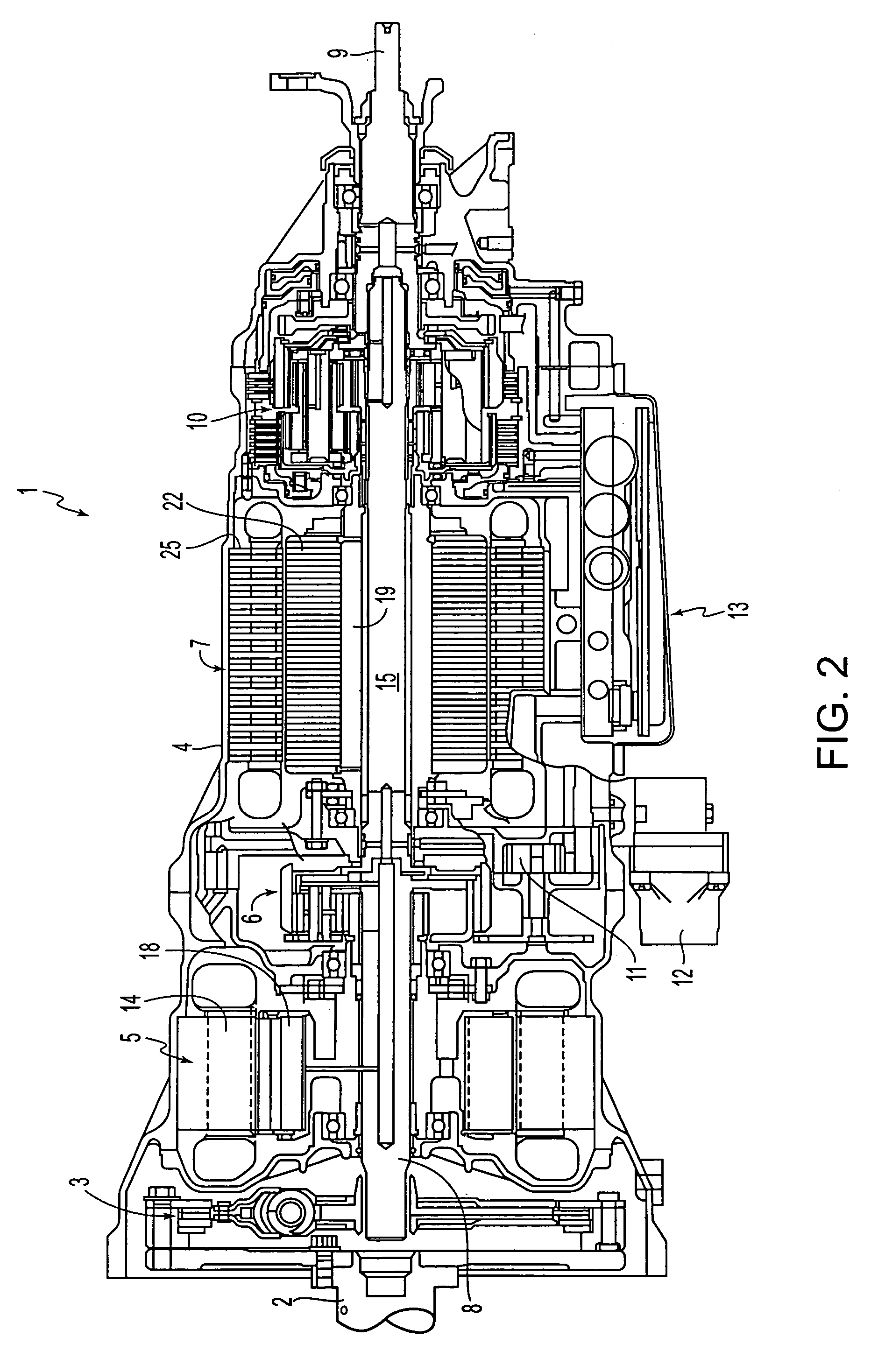
[0025]First, the detailed structure of a form of the drive unit of the invention of a vehicle will be explained using FIG. 2. As shown in FIG. 2, the drive unit 1 for a vehicle is structured as a 2-motor split hybrid type. The drive unit 1 has a damper device 3, a first motor (motor-generator) 5, a power distributing planetary gear 6, a second motor (drive motor) 7, and a speed change gear 10 able to change driving force of the second motor 7 and transmit this drive force to an output shaft 9. These members are aligned with a crank shaft 2 from the side of an internal combustion engine E (see FIG. 1) and are sequentially arranged in a uniaxial shape within a case 4.

[0026]An input shaft 8 is arranged in the inner circumferential portions of the first motor 5 and the power distributing planetary gear 6 and is aligned with the crank shaft 2 in the uniaxial shape. An intermediate shaft (drive shaft) 15 connected to the input shaft 8 through the power distributing planetary gear 6 and ex...


PUM


Abstract

A drive unit for a vehicle structured so as to be able to attain an interrupting state of inertia of a drive motor under a predetermined condition. Therefore, the drive unit for a vehicle has a drive motor able to transmit driving force to a drive wheel, and an operation lever for selecting a shift range for switching the drive motor between drive and non-drive. Further, the drive unit for a vehicle has a control section having a shift position detector for detecting the shift range selected by the operation lever. The drive unit for a vehicle also has brakes for attaining a neutral state by interrupting the power transmission between the drive motor and the drive wheel when the selection of a parking range is detected by the shift position detector.

Description

[0001]This application claims priority from JP 2003-153119 filed May 29, 2003, the disclosure of which is incorporated in its entirety herein by reference thereto.BACKGROUND OF THE INVENTION[0002]1. Field of Invention[0003]The invention relates to a drive unit of a vehicle, such as an electric automobile (EV) having at least a drive motor, a hybrid car (HEV), etc., and particularly relates to a drive unit improved such that no excessive inertia caused by the existence of the drive motor is applied to a parking device under a predetermined condition when a parking operation is performed.[0004]2. Description of Related Art[0005]A drive unit of a so-called 2-motor split type is conventionally mounted in an automobile (registered trademark Prius) and is practically used as a hybrid drive unit. Although discussed in the context of an automobile, the drive unit can be used with other types of wheeled vehicles. In this hybrid drive unit, an output from an engine is distributed to a motor (...

Claims


Application Information

Patent Timeline
Patent Type & Authority Patents(United States)
IPC IPC(8): F16H3/72B60K6/365B60K6/40B60K6/445B60K6/547B60K17/04B60L50/16B60W10/06B60W10/08B60W10/10B60W20/00F16H59/08F16H61/02F16H61/68F16H61/684F16H61/686F16H63/48
CPCB60K6/365B60K6/445B60W10/06B60W10/08F16H63/483B60W20/00Y10T477/20F16H2037/0873Y02T10/6286Y02T10/6239Y02T10/62B60W20/15B60K6/36
Inventor MIURA, KIYOTOMOOMOTE, KENJIWAKUTA, SATORUMOTOIKE, KAZUTOSHIADACHI, MASATOSHI
Owner AISIN AW CO LTD
Learn More