Method and device for retrieving embolic coils

a coil and coil technology, applied in the field of methods and devices for retrieving embolic coils, can solve the problems of increasing the procedure time and affecting the patient, and the protrusion of coils can have a disastrous effect on the patien

Inactive Publication Date: 2007-04-10
CODMAN & SHURTLEFF INC
View PDF20 Cites 88 Cited by
  • Summary
  • Abstract
  • Description
  • Claims
  • Application Information

AI Technical Summary

Problems solved by technology

This coil protrusion can have a disastrous effect on the patient.
Since the misplaced coil is sometimes a loop, the physician often has difficulty trying to lasso these coils which may add to the procedure time and cause potential complications.

Method used


Image

  • Method and device for retrieving embolic coils
  • Method and device for retrieving embolic coils
  • Method and device for retrieving embolic coils

Examples


Embodiment Construction

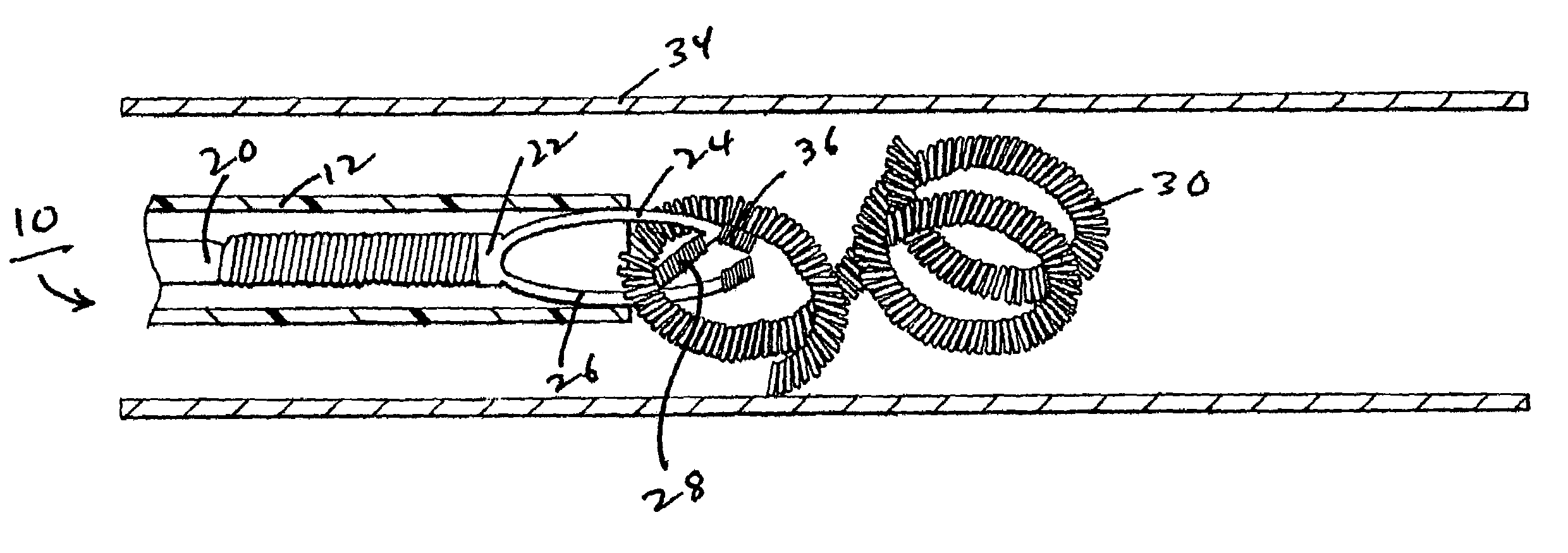
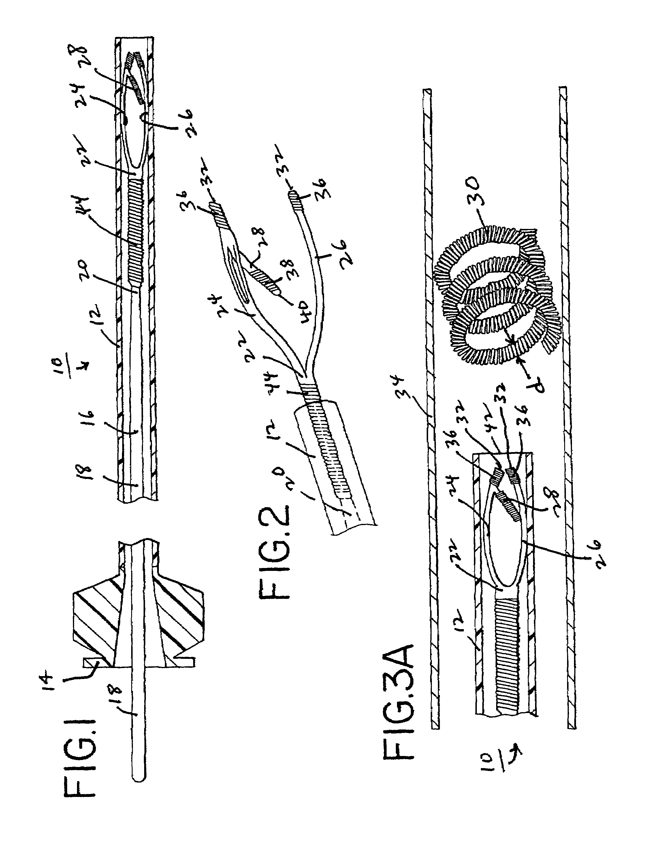
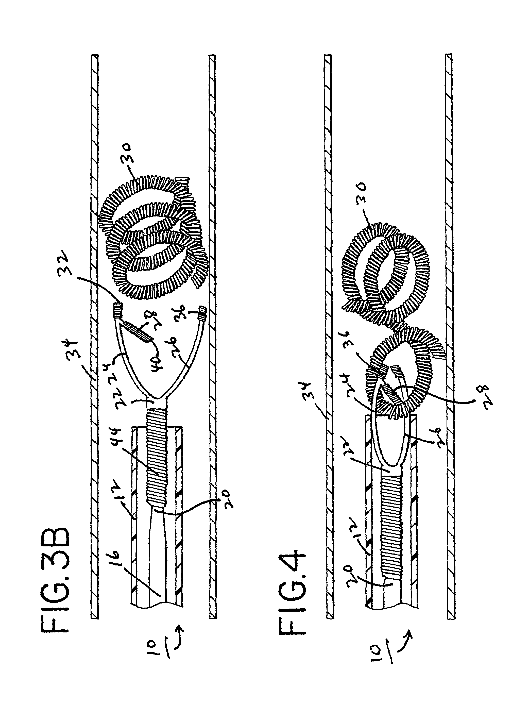
[0020]Referring to FIG. 1, an embolic coil retrieval system 10 is shown therein. System 10 includes a microcatheter 12 formed of a polymeric material as is known in the art, the proximal end 14 of which comprises a luer connector. Except for the proximal end of the microcatheter 12, the remaining portions of the microcatheter are preferably uniform. Although no limitation is intended, as a specific example, the inner diameter of the catheter is preferably between 0.010 inch and 0.025 inch, and the outer diameter of the catheter is preferably between 0.030 inch and 0.050 inch.

[0021]Positioned within microcatheter 12 is a wire device 16, which wire device 16 has pushability with respect to the catheter so that it can be manipulated like a guidewire. The proximal portion 18 of the wire device 16 is generally uniform but the wire device becomes tapered at a distal portion 20 which connects to a headpiece 22 including a pair of arms 24, 26. Proximal portion 18 of the wire device 16 is st...


PUM


Abstract

A method and device are disclosed for retrieving embolic coils used for treating an aneurysm of a patient. The method comprises the steps of providing a wire device that is pushable through a microcatheter and has a flexible distal portion comprising distal collapsible arms with a latch member carried by one of the arms. The microcatheter is introduced into a patient's vessel leading to the aneurysm. The wire device, distal end first, is introduced into the microcatheter whereby the arms collapse while they are within the microcatheter. The distal end of the wire device is pushed through the microcatheter whereby the arms open when they extend out of the distal end of the microcatheter. The latch member is manipulated so that it engages an embolic coil to be retrieved. The latch-engaged embolic coil and wire device are withdrawn through the catheter, whereby the arms become collapsed as the arm is withdrawn through the catheter, securing the latch and the embolic coil.

Description

[0001]This patent application is a divisional patent application of U.S. patent application Ser. No. 09 / 865,642, filed May 25, 2001.FIELD OF THE INVENTION[0002]The present invention concerns a novel method and device for retrieving embolic coils used for treating an aneurysm of a patient.BACKGROUND OF THE INVENTION[0003]A well known method of treating an aneurysm of a vessel wall includes the placement of a number of detachable embolic coils within the aneurysm. Multiple coils are employed during the procedure in an effort to completely embolize the vessel defect. Typically, a deployment device is used to introduce the coils, one by one, via a microcatheter, into the aneurysm. Occasionally during a procedure, an earlier introduced coil may become displaced from the aneurysm and protrude into the parent vessel. This coil protrusion can have a disastrous effect on the patient. Because the embolic coil is in the blood flow, thrombus begins to form around the coil which can potentially ...

Claims


Application Information

Patent Timeline
Patent Type & Authority Patents(United States)
IPC IPC(8): A61F2/06A61B17/00A61B17/076A61B17/12A61B17/22A61B17/28A61B17/30A61B17/50A61B19/00
CPCA61B17/12022A61B17/12113A61B17/1214A61B17/221A61B17/076A61B17/282A61B17/30A61B19/54A61B2017/1205A61B2017/22035A61B2017/2215A61B2017/2825A61B90/39
Inventor DIAZ, ROBERTOMITELBERG, VLADIMIR
Owner CODMAN & SHURTLEFF INC
Why Eureka
Try Eureka