Small-hole electrical discharge machining device and multiple diesinking-and-small-hole electrical discharge machining device, and method for multiple diesinking-and-small-hole electrical discharge machining with the same device

a technology diesinking, which is applied in the direction of electrical-based machining electrodes, vibration holders of electrical devices, manufacturing tools, etc., can solve the problems of difficult preparation of programs, difficult to execute automatic continuous operation of electrical discharge machining, and longer total machining tim

Active Publication Date: 2007-04-10
ELENIX KK
View PDF17 Cites 11 Cited by
  • Summary
  • Abstract
  • Description
  • Claims
  • Application Information

AI Technical Summary

Benefits of technology

[0024]FIG. 10 is an exemplary view explaining a configuration of a multiple diesinking and small-hole electrical discharge machining device by six-axes (X, Y, W, Z, A, B) control according to the present invention; and
[0025]FIG. 11A shows an example of an electrode which is used when diesinking electrical discharge machining and small-hole electrical discharge machining are simultaneously executed, and is a sectional view of the electrode for machining the counter boring hole shown in FIG. 1A;
[0026]FIG. 11B shows an example

Problems solved by technology

Accordingly, it is difficult to execute automatic continuous operation for electrical discharge machining.
However, even in this method, it is difficult to prepare programs when a work has a complex shape.
A

Method used


Image

  • Small-hole electrical discharge machining device and multiple diesinking-and-small-hole electrical discharge machining device, and method for multiple diesinking-and-small-hole electrical discharge machining with the same device
  • Small-hole electrical discharge machining device and multiple diesinking-and-small-hole electrical discharge machining device, and method for multiple diesinking-and-small-hole electrical discharge machining with the same device
  • Small-hole electrical discharge machining device and multiple diesinking-and-small-hole electrical discharge machining device, and method for multiple diesinking-and-small-hole electrical discharge machining with the same device

Examples


Embodiment Construction

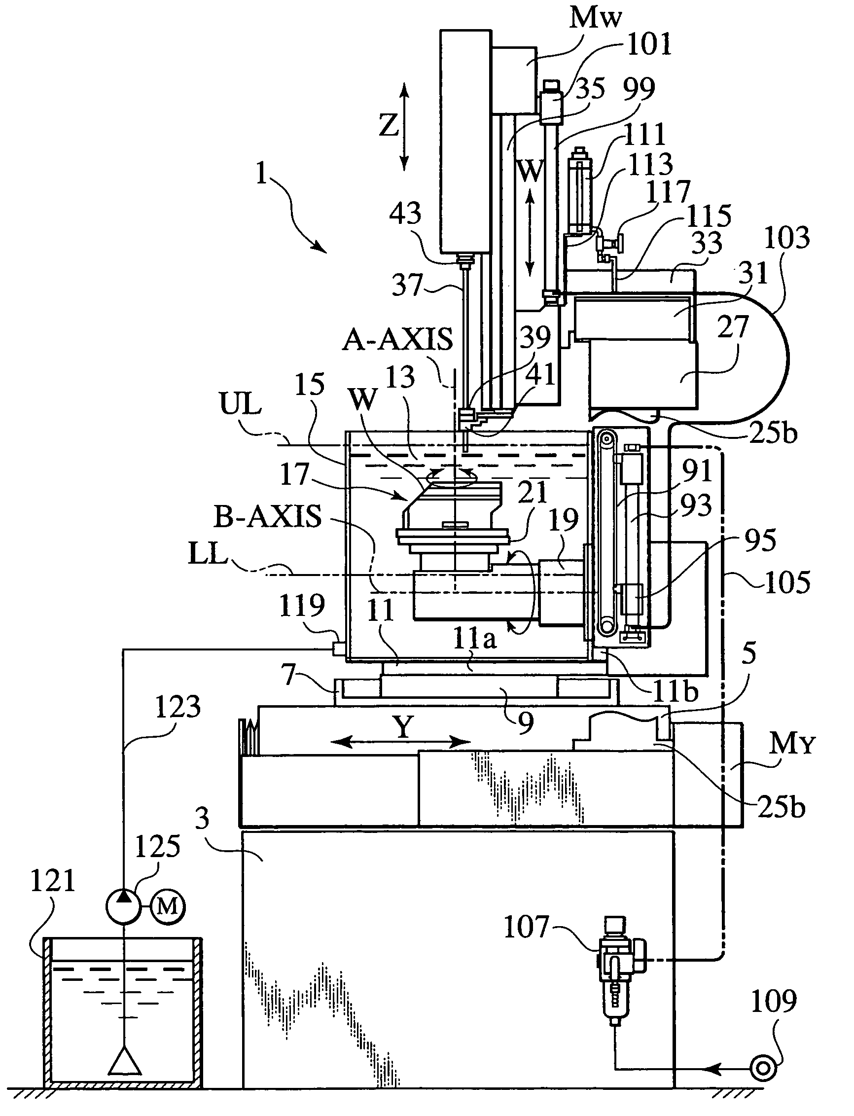
[0028]Hereinafter, one embodiment according to the present invention will be explained, referring to drawings. Here, it is assumed hereafter that the right and left direction, the up and down one, and the back and forth one with regard to the printed surface in FIG. 4 are the X-axis direction, the Z-axis one, and the Y-axis one, respectively.

[0029]With reference to FIGS. 4 and 5, a Y-axis table 5 which can be moved and positioned in the Y-axis direction by a driving unit (not shown), and a Y-axis drive motor MY is provided on a base 3 of a small-hole electrical discharge machining device 1.

[0030]The Y-axis table 5 further comprises a pan 7 which is integrally provided with the table 5, a bed 9 which is made of an insulating material and is provided on the pan 7, and an L-shaped bracket 11 which is integrally provided on the bed 9.

[0031]A work tank 15 being filling with a working fluid 13 such as pure water with a small electrical conductivity is installed on the L-shaped bracket 11,...


PUM

PropertyMeasurementUnit
Depthaaaaaaaaaa
Distanceaaaaaaaaaa
Levelaaaaaaaaaa

Abstract

A small-hole electrical discharge machining device comprises a diaphragm which can be moved up and down along a notch window provided in a work tank for mounting a work in the work tank in which a working fluid can be filled or discharged, and adjusts the height of the working fluid; a W-axis slide which can be moved up and down, and having an electrode guide in the lower end portion; a master cylinder which is moved up and down corresponding to up-and-down movement of the W-axis slide; and a slave cylinder which is connected with the master cylinder through a pipeline and with a diaphragm driving mechanism, and wherein the diaphragm is moved up and down corresponding to up and down movement of the W-axis slide.

Description

CROSS REFERENCE TO RELATED APPLICATIONS[0001]This application is based upon and claims the benefit of priority from the Japanese Patent Applications No. 2003-172125, filed on Jun. 17, 2003 in the Japanese Patent office; the entire contents of which are incorporated herein by reference.BACKGROUND OF THE INVENTION[0002]1. Field of the Invention[0003]This invention relates to a small-hole electrical discharge machining device and a multiple diesinking-and-small-hole electrical discharge machining device, and a method of multiple diesinking-and-small-hole electrical discharge machining by using the same device.[0004]2. Description of the Related Art[0005]There is a demand for electrical discharging machining on a various face of a work to be machined in a work tank which is filled with a working fluid comprising oil and water. In such case, heretofore, a small-hole electrical discharge machining device having a work tank which can be freely tilted by a turntable, in other words the work...

Claims


Application Information

Patent Timeline
IPC IPC(8): B23H1/10B23H7/36B23H7/10B23H7/26B23H9/14
CPCB23H1/10B23H7/101B23H7/36B23H7/26Y10T137/86236
Inventor ISHIWATA, HIROSHIYOKOMICHI, SHIGEHARU
Owner ELENIX KK
Why Eureka
Try Eureka