Imaging apparatus and imaging method

a technology of imaging apparatus and image, applied in the field of imaging apparatus, can solve the problems of degrading the graininess of the image, increasing the whitened portion, and affecting the image quality,

Active Publication Date: 2007-04-10
RICOH KK
View PDF28 Cites 20 Cited by
  • Summary
  • Abstract
  • Description
  • Claims
  • Application Information

AI Technical Summary

Benefits of technology

[0053]The threshold value may be determined by weighting the coefficient depending on the scanning direction so t...

Problems solved by technology

However, in a printer with low resolution, big dots are output for the highlighted portions of the image and the dots are spaced apart from each other, causing the isolated dots to stand out, and thereby degrading the graininess of the image.
In the region close to the gray scale value 0 (gray scale value 1) awkwardness arising from graininess is not really a problem; instead, the problem lies in the delay of the dots being produced in the error diffusion process which results in an increase in the whitened portion.
Due to the delay in the generation of dots at the switchover regions of the 4-level quantization output values, a gray scale gap (contour) is created at the switchover regions, thereby degrading the image quality.
The gaps (contours) in the gray scale representation created in these regions (the switchover regions of the N-level quantization output value) are the causes of the image quality degradation.
The above-mentioned conventional art techniques solve the problem of dis...

Method used


Image

  • Imaging apparatus and imaging method
  • Imaging apparatus and imaging method
  • Imaging apparatus and imaging method

Examples


embodiment 1

[0126](Embodiment 1)

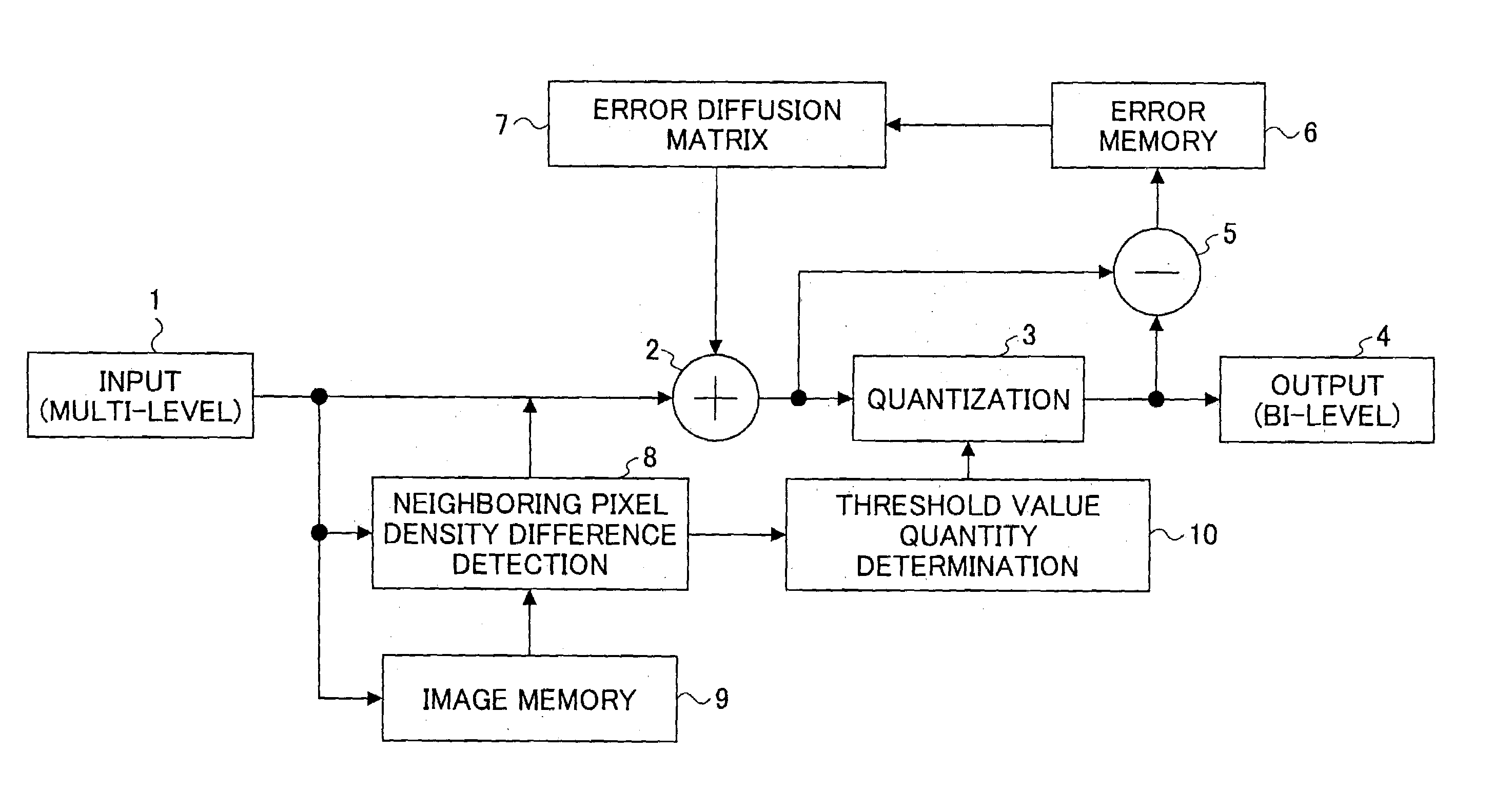
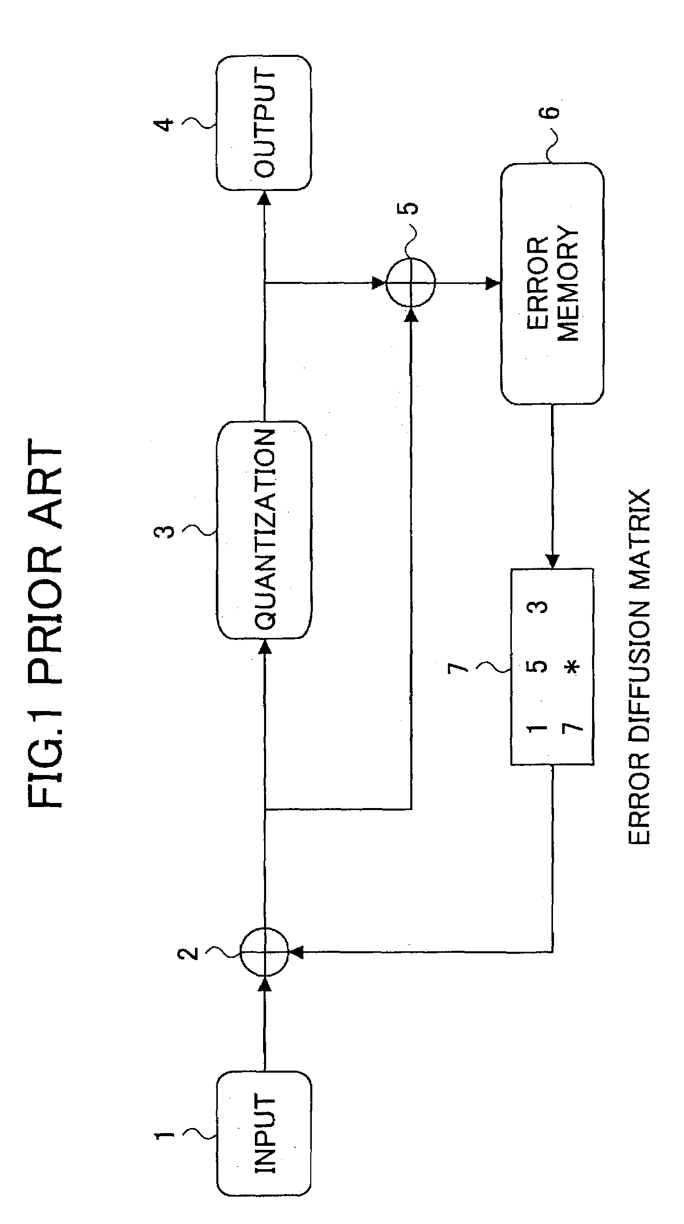
[0127]FIG. 21 is a diagram illustrating the configuration of a bi-level error diffusion process according to a first embodiment of the present invention. In this drawing, the input (multi-level) 1, the adder 2, the quantization part (bi-level) 3, the output 4 (bi-level), the subtractor 5, the error memory 6, and the error diffusion matrix 7 are the same as those of the conventional art shown in FIG. 1. In the present invention, a neighboring pixel density difference detection part 8, an image memory 9, and a threshold value quantity determination part 10 are added to the configuration.

[0128]In the following, the operation of the error diffusion process according to the first embodiment, wherein the threshold values shown in FIG. 6 are used and the threshold value corresponding to the adjacent pixels of FIG. 18 is implemented, is described. FIG. 22 is a process flowchart of the first embodiment of the present invention. First, image data for two lines are stored i...

embodiment 2

[0134](Embodiment 2)

[0135]In the above-described first embodiment, the threshold value varying in accordance with the input value (density) as shown in FIG. 6 is used and the sharpness can be controlled by determining the threshold value corresponding to the density of a neighboring pixel. However, the emphasizing effect depends on the inclination of the threshold value of FIG. 6.

[0136]Depending on the image design, there are instances in which greater emphasis on sharpness is demanded in the image, and there are instances in which the emphasizing effect is not greatly demanded. Thus, in a case where greater emphasis is demanded, the threshold value can be lowered when the edge has a raised density and the threshold value can be raised when the edge has a lowered density. On the other hand, in a case where emphasis is not greatly demanded, the threshold value is set slightly higher when the edge has a raised density and the threshold value is set slightly lower when the edge has a l...

embodiment 3

[0143](Embodiment 3)

[0144]In an output apparatus that has different reproducibility of thin lines depending on the scanning direction (primary scanning or sub scanning) such as the electrophotographic imaging apparatus, the emphasizing effect controlling coefficient α for the primary scanning and that for the sub scanning are preferably varied. In such a case, the predetermined coefficient for controlling the emphasis level being denoted as α, individual coefficients are assigned to each of the primary scanning and the sub scanning and a different coefficient α is used for each of the different scanning directions.

[0145]FIG. 29 shows the configuration of the third embodiment of the present invention. The difference between the second and third embodiment is that in the third embodiment, a signal for selecting either a coefficient α1 or α2 is sent to the secondary threshold value quantity determination part 10b from the detection part 8. That is, the detection part 8 notifies the sec...


PUM


Abstract

The present invention accurately reproduces an image pattern by referring to neighboring pixels upon determining the threshold value of a target pixel so that a delay in dot generation can be prevented while emphasizing an image transition portion so that both graininess and sharpness are improved in the image. To this end, a neighboring pixel density difference detection part obtains an absolute value of the density difference between a target pixel and its neighboring pixels and selects the density of a neighboring pixel with a large absolute value as a reference pixel density. Further, a threshold value quantity determination part determines a threshold value corresponding to the density selected by the neighboring pixel density difference detection part. Then, a quantization part outputs an output value based on a comparison between the threshold value and a corrected value obtained by adding a pre-calculated error value of neighboring pixels to an input value.

Description

BACKGROUND OF THE INVENTION[0001]1. Field of the Invention[0002]The present invention relates to an imaging apparatus that performs an error diffusion process on image data with M gray levels to reproduce an N-level dot image (M>N), the technology being suitable for application in printers, digital copiers, facsimile machines, and the like.[0003]2. Related Art[0004]The imaging quality of printers and the speed of personal computers have significantly improved over the past few years. Particularly, the output resolution of printers has reached a high of 1200×1200 dpi, and some printers are capable of changing the output dot size from a choice of small, medium, to large dots. Achieving a higher resolution in ink jet printers involves increasing the density of the ink heads that spray ink and improving the performance of paper conveyances, or preventing the sprayed ink from spreading on the paper by using ink with high viscosity, for example, and controlling the amount of ink coming...

Claims


Application Information

Patent Timeline
IPC IPC(8): G06K9/36G06K9/38B41J2/52G06T5/00H04N1/40H04N1/405
CPCH04N1/40087H04N1/4053
Inventor TAKAHASHI, HIROSHIOGAWA, TAKESHI
Owner RICOH KK
Why Eureka
Try Eureka