Image heating apparatus and heater for use therein

a heating apparatus and image technology, applied in the field of image heating apparatus and heater for use therein, can solve the problems of high-temperature offset phenomenon, temperature increase, and temperature increase in an area, and achieve the effect of suppressing an uneven temperature distribution and reducing the number of output sheets

Active Publication Date: 2007-04-10
CANON KK
View PDF28 Cites 55 Cited by
  • Summary
  • Abstract
  • Description
  • Claims
  • Application Information

AI Technical Summary

Benefits of technology

[0019]Another object of the present invention is to provide an image heating apparatus capable of suppressing a decrease in the number of output sheets per unit time and a heater adapted for use in such apparatus.
[0020]Still another object of the present invention is to provide an image heating apparatus capable of suppressing an unevenness in the temperature distribution in the longitudinal direction of the heater while exploiting the advantages of the heater of sheet-passing-direction current-feed type, and a heater adapted for use in such heater.

Problems solved by technology

However, in case of a continuous printing operation on small-sized sheets, there results a phenomenon of gradual temperature increase in an area not passed by the paper in the longitudinal direction of the fixing nip portion (temperature increase in sheet non-passing area).
An excessively high temperature in the sheet non-passing area causes damages in various parts in the apparatus, and a printing operation on a large-sized sheet in a state with the temperature increase in the sheet non-passing area results in a high-temperature offset phenomenon in an area corresponding to the sheet non-passing area for the small-sized sheet.
As a countermeasure for such excessive temperature increase in the sheet non-passing area, it is conceived to provide the heater substrate with plural heat generating members corresponding to the sizes of the recording sheets used on the printer, but such method of forming plural heat generating members corresponding to the number of sizes is impractical as the recording sheets used on the printer have very many sizes.
Also there can be conceived a method, in a continuous printing operation on small-sized sheets, of increasing a gap between a preceding sheet and a succeeding sheet thereby relaxing the excessive temperature increase in the sheet non-passing area, but such method is associated with a drawback of significantly decreasing the number of the output sheets per unit time.
It is found, however, that such heater, when actually mounted in the fixing device, causes an unevenness in the distribution of heat generation in the longitudinal direction of the heater even when sheets are not passed.

Method used


Image

  • Image heating apparatus and heater for use therein
  • Image heating apparatus and heater for use therein
  • Image heating apparatus and heater for use therein

Examples


embodiment 1

[0051](Embodiment 1)

[0052](1) Example of Image Forming Apparatus

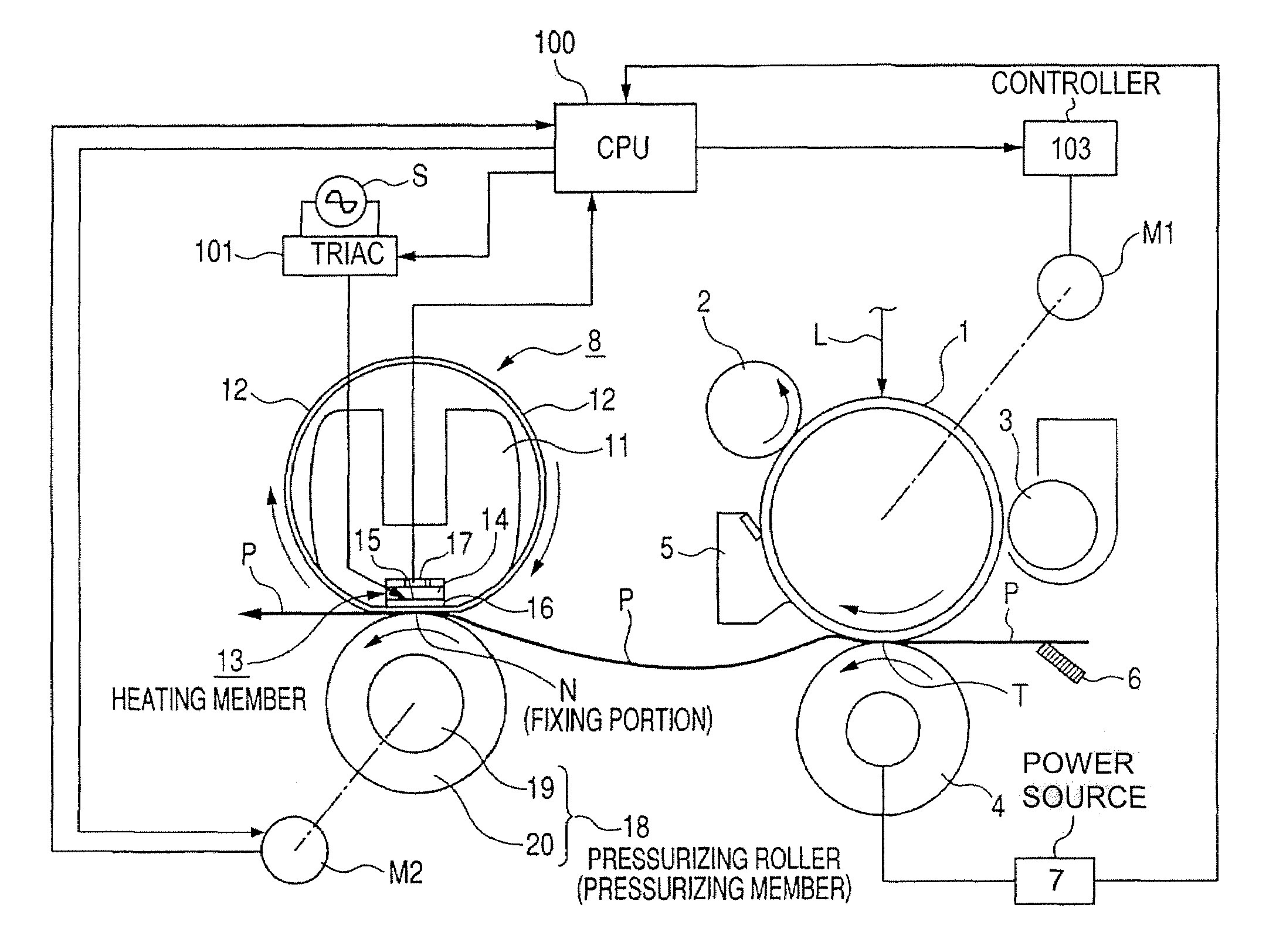
[0053]FIG. 1 is a schematic view showing a configuration of an image forming apparatus. The image forming apparatus of the present embodiment is a copying apparatus or a printer utilizing an electrophotographic process of transfer type. In the image forming apparatus of the present embodiment, a largest usable recording material is of a letter size (216×279 mm), and the recording material of such letter size can be conveyed with the longer side (279 mm) thereof parallel to the conveying direction. Also conveying of the recording material is executed taking, as a reference, a longitudinal center of a heat generating resistor of a fixing apparatus to be explained later.

[0054]An electrophotographic photosensitive member 1 of a drum shape (hereinafter represented as photosensitive drum) serves as a latent image bearing member and is rotated with a predetermined process speed, in a clockwise direction as indicated by an arro...

embodiment 2

[0101](Embodiment 2)

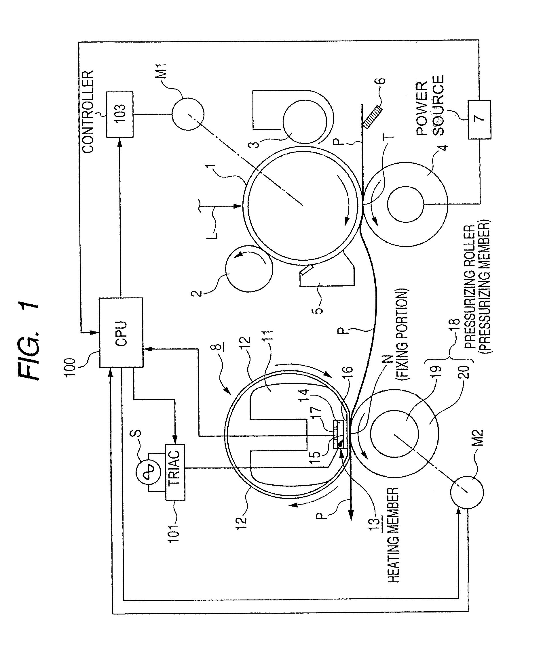
[0102]In the embodiment 1, as explained in the foregoing, within the second area 21b of the first electrode 21, a portion electrically closest to the first area 21a of the first electrode 21 (a portion X in FIG. 2) is provided in the vicinity of an end (right-hand end in FIG. 2) of the substrate 14 in the longitudinal direction thereof, and, within the second area 22b of the second electrode 22, a portion electrically closest to the first area 22a of the second electrode 22 (a portion Y in FIG. 2) is provided in the vicinity of the other end (left-hand end in FIG. 2) of the substrate 14 in the longitudinal direction thereof. Thus, in the heater of the embodiment 1, the current entrances from the electrodes to the heat generating resistor are separated at both ends of the substrate in the longitudinal direction thereof.

[0103]On the other hand, in the embodiment 2, within the second areas 21b, 22b of the first electrode 21 and the second electrode 22, portions elec...

embodiment 3

[0120](Embodiment 3)

[0121]In the following, there will be explained a third embodiment of the present invention.

[0122]In FIG. 13, (a) and (b) are magnified views respectively of a top surface and a rear surface of a heater 13 in an image heating apparatus of the present embodiment. On a substrate 14, electrodes and a heat generating resistor have shapes and functions basically same as those in the embodiment 1 shown in FIG. 2.

[0123]In the present embodiment, there is defined a relationship between a resistance value Rt (hereinafter called total resistance value) from a portion, within the second area of the first electrode, electrically closest to the first area of the first electrode, to a portion, within the second area of the second electrode, electrically closest to the first area of the second electrode, and a resistance value Rc of the second area of an electrode.

[0124]As already explained in the embodiment 1, when the heater is at the set temperature (fixing temperature) of t...


PUM


Abstract

Image heating apparatus capable of preventing an excessive temperature increase in a sheet non-passing area and heater for use in the image heating apparatus including: a substrate, a heat generating resistor formed on the substrate, and first and second electrodes for supplying an electric power to the heat generating resistor. Each of the first and second electrodes has a first area to contact a power supplying connector and a second area provided at an end portion electrically opposite to the first area along a longitudinal direction of the substrate, and the heat generating resistor is provided to electrically connect the second area of the first and second electrode so that when the heater is at a set temperature for an image heating operation a resistance value Rc of the second area, and a resistance value Rt between a portion within the second area of the first and second electrode and electrically closest to the first area satisfy a relation Rc / Rt<=1 / 30.

Description

CROSS REFERENCE TO RELATED APPLICATION[0001]This application claims priority from Japanese Patent Application Nos. 2004-015173 filed Jan. 23, 2004 and 2005-002697 filed Jan. 7, 2005, which are hereby incorporated by reference herein.BACKGROUND OF THE INVENTION[0002]1. Field of the Invention[0003]The present invention relates to an image heating apparatus adapted for use as a heat fixing apparatus to be mounted in a copying apparatus or a printer utilizing an electrophotographic recording technology or an electrostatic recording technology and a heater to be used in such apparatus, and more particularly to an image heating apparatus for heating an image by passing a recording material, bearing an image, through a nip portion between a heater and a backup member and a heater to be used in such apparatus.[0004]2. Related Background Art[0005]In the following, there will be explained an example of a prior image heating apparatus equipped in an image forming apparatus such as a copying ap...

Claims


Application Information

Patent Timeline
Patent Type & Authority Patents(United States)
IPC IPC(8): G03G15/20H05B3/00H05B3/03H05B3/12
CPCH05B3/0095G03G15/2042G03G15/2053G03G2215/2016
Inventor OMATA, MASAHITONAKAHARA, HISASHINAKAZONO, YUSUKENISHIDA, SATOSHIUEKAWA, EIJITAKEDA, ISAMUITO, NORIYUKI
Owner CANON KK
Why Eureka
Try Eureka