Fastener for fixed rib applications

a technology for fixing ribs and fasteners, which is applied in the direction of threaded fasteners, screwdrivers, couplings, etc., can solve the problems of inability of the fastener to seal for moisture intrusion, dust and dirt into the automobile, and the need for plating and/or finishing to prevent corrosion, so as to reduce the potential for corrosion and reduce the installation time, effort and cost

Active Publication Date: 2007-04-17
NEWFREY
View PDF15 Cites 26 Cited by
  • Summary
  • Abstract
  • Description
  • Claims
  • Application Information

AI Technical Summary

Benefits of technology

[0007]An advantage of the present invention over traditional fasteners includes provision of the polymeric portion that provides flexibility at a seal joint between the fastener and the vehicle or trim piece and reduces the potential for corrosion by eliminating metal-to-metal contact at the seal joint. The present fastener having a metallic portion including deflection members provides spring force for retention of the fastener. The present invention unitary fastener also reduces installation time, effort and cost.
[0008]Further areas of applicability of the present invention will become apparent from the detailed description provided hereinafter. It should be understood that the detailed description and specific examples, while indicating the preferred embodiment of the invention, are intended for purposes of illustration only and are not intended to limit the scope of the invention.

Problems solved by technology

A drawback of commonly used fasteners is the inability of the fastener to seal for intrusion of moisture, dust and dirt into the automobile.
Another drawback in an all-metal fastener or retainer is that because of the materials used, a plating and / or finish is required to prevent corrosion.
Still another drawback of some existing fastener designs is an all metal body of the fastener itself.
An all-metal fastener can result in corrosion between the metal contact surfaces of the fastener and the automobile as well as causing damage to the area of the aperture of the automobile upon insertion of the fastener or removal of the fastener.
Some fastener designs have a further drawback by requiring two pieces.
This obviously increases complexity and cost of assembly as well as requiring maintenance of a two part system during vehicle construction.

Method used


Image

  • Fastener for fixed rib applications
  • Fastener for fixed rib applications
  • Fastener for fixed rib applications

Examples


Embodiment Construction

[0017]The following description of the preferred embodiment is merely exemplary in nature and is in no way intended to limit the invention, its application, or uses.

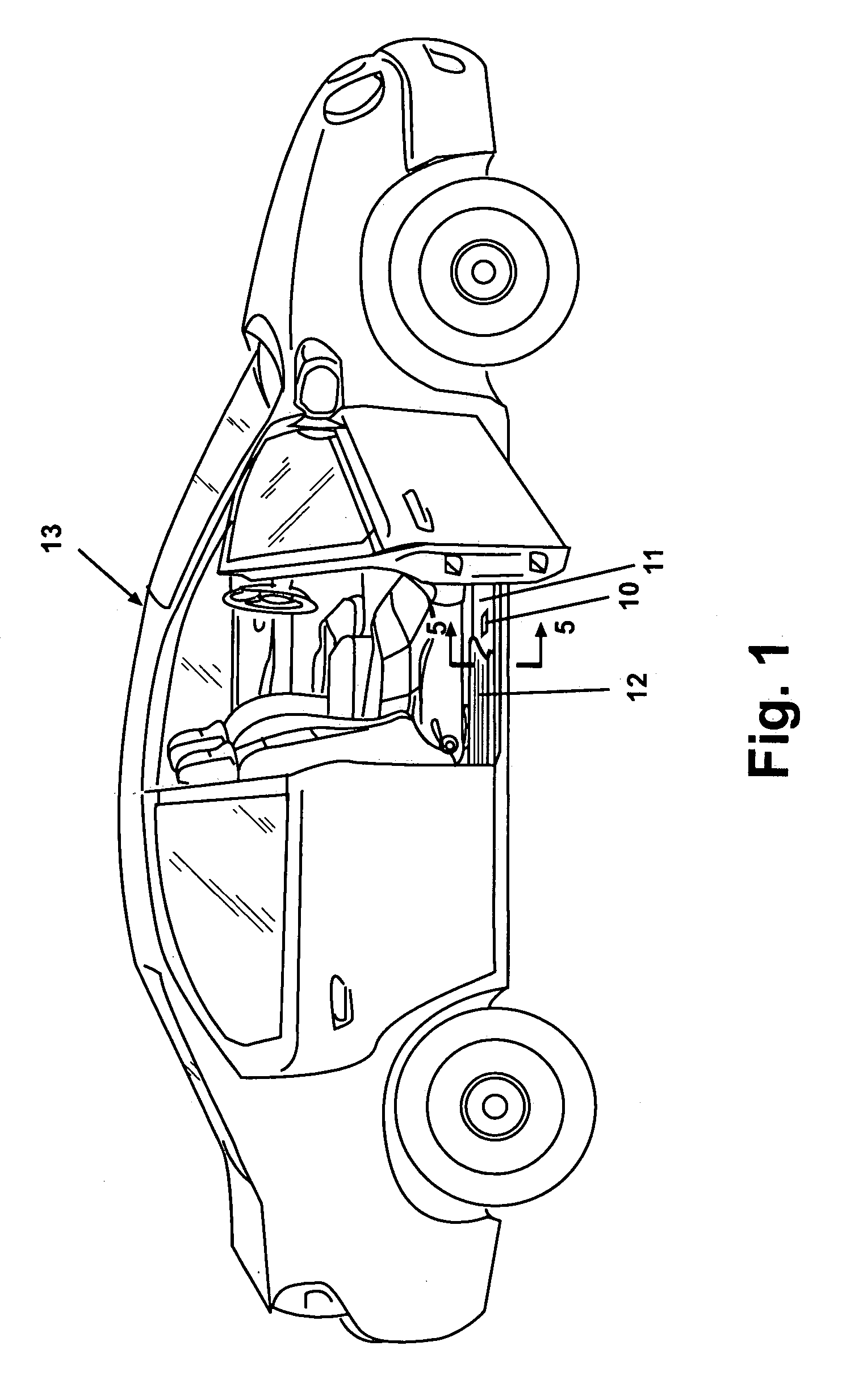
[0018]According to the preferred embodiment of the present invention and as shown in FIG. 1, a fastener 10 is positionable between a rocker panel sill plate 11 and a sill plate molding 12 (or trim piece) to retain the sill plate molding 12 in position adjacent sill plate 11 of an automobile 13. In the embodiment shown in FIG. 1, fastener 10 retains sill plate molding 12 adjacent the floor area or seating compartment of automobile 13. Fastener 10 is not limited to an application for installation of sill plate moldings to sill plates, but can be used for any application of a trim or molding piece to automobile 13 or a vehicle.

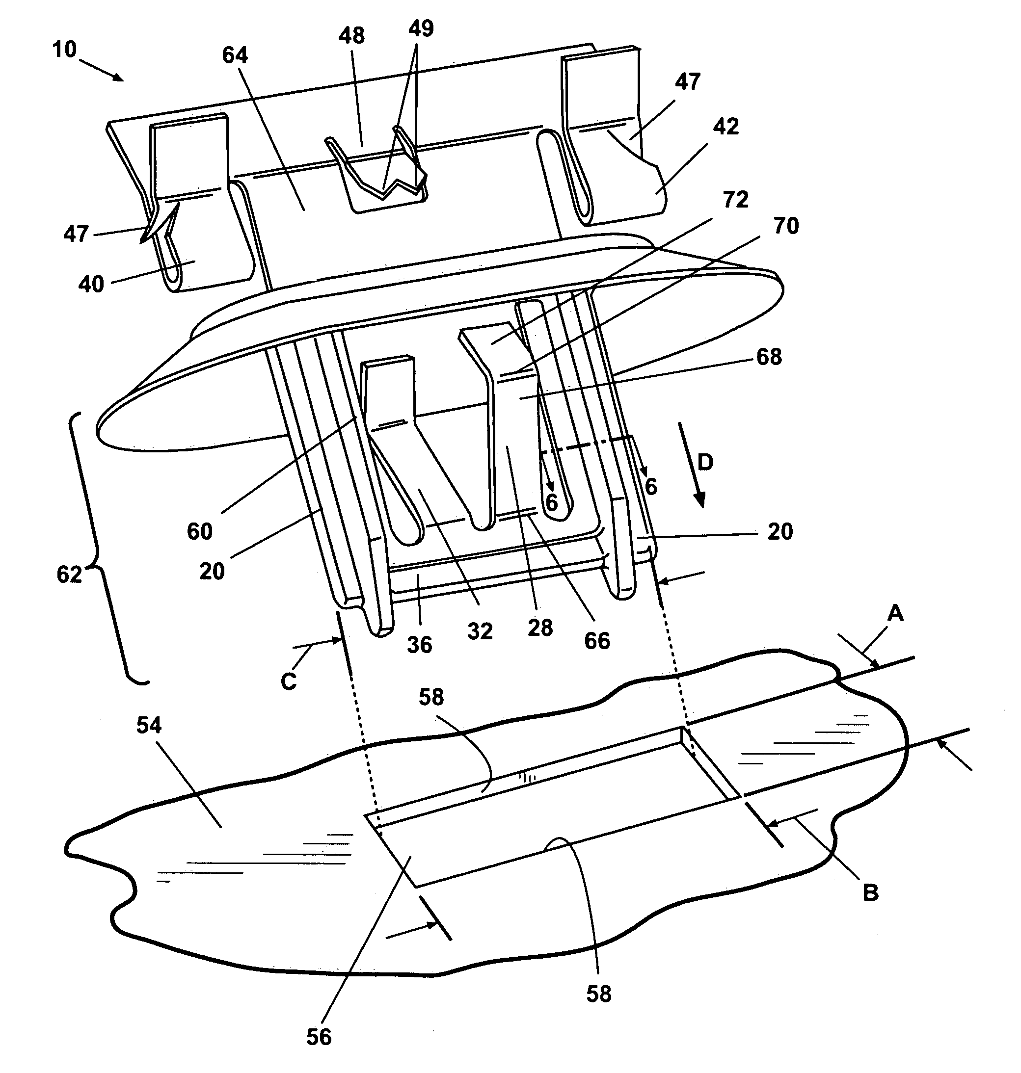
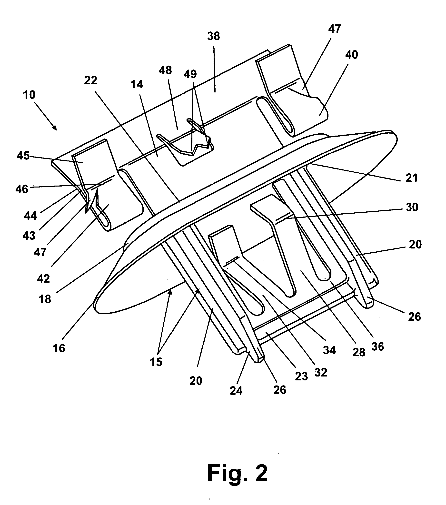
[0019]Referring to FIG. 2, fastener 10 includes a metallic portion 14 which is insert molded with a molded portion 15. Insert molding, as referred to herein, includes insertion of the metallic portion...


PUM


Abstract

A fastener joining accessories to automobiles includes a molded portion having a flexible skirt and two support posts extending from the flexible skirt. A metallic portion insert molded with the molded portion includes both a pair of deflection wings and a pair of looped bights oppositely extending from the flexible skirt.

Description

FIELD OF THE INVENTION[0001]The present invention relates generally to fasteners and more specifically to a fastener design for joining trim pieces to the surfaces of automobiles.BACKGROUND OF THE INVENTION[0002]For automotive applications, fasteners are used to join trim pieces to sections or metal body portions of the automobile. The requirements for these fasteners are that they be insertable into apertures of the automobile and meet standards for both insertion pressure of the insert as well as minimum pullout retention force such that the insert can be removed without damaging the trim piece. Common fastener designs include two or more flexible wings which deflect upon insertion of the fastener and expand by spring force to hold the fastener within an aperture formed in the automobile. A drawback of commonly used fasteners is the inability of the fastener to seal for intrusion of moisture, dust and dirt into the automobile. Another drawback in an all-metal fastener or retainer ...

Claims


Application Information

Patent Timeline
Patent Type & Authority Patents(United States)
IPC IPC(8): A44B1/04B60R13/02F16B5/12F16B19/00F16B21/08
CPCF16B5/123F16B21/075B60R13/0206Y10T24/309Y10T403/606Y10T24/304Y10T24/307
Inventor BENEDETTI, STEVEN MNESSEL, ROSALIND A
Owner NEWFREY
Why Eureka
Try Eureka