High-pressure plug valve

a plug valve and high-pressure technology, applied in the direction of plug valves, valve arrangements, thin material handling, etc., can solve the problems of reducing the service life of the plug valve, so as to improve the service life and improve the service life.

a plug valve and high-pressure technology, applied in the direction of plug valves, valve arrangements, thin material handling, etc., can solve the problems of reducing the service life of the plug valve, so as to improve the service life and improve the service life.

US7204474B2Active Publication Date: 2007-04-17WELLS FARGO BANK NAT ASSOC +1

Image

  • High-pressure plug valve
  • High-pressure plug valve
  • High-pressure plug valve

Examples


Embodiment Construction

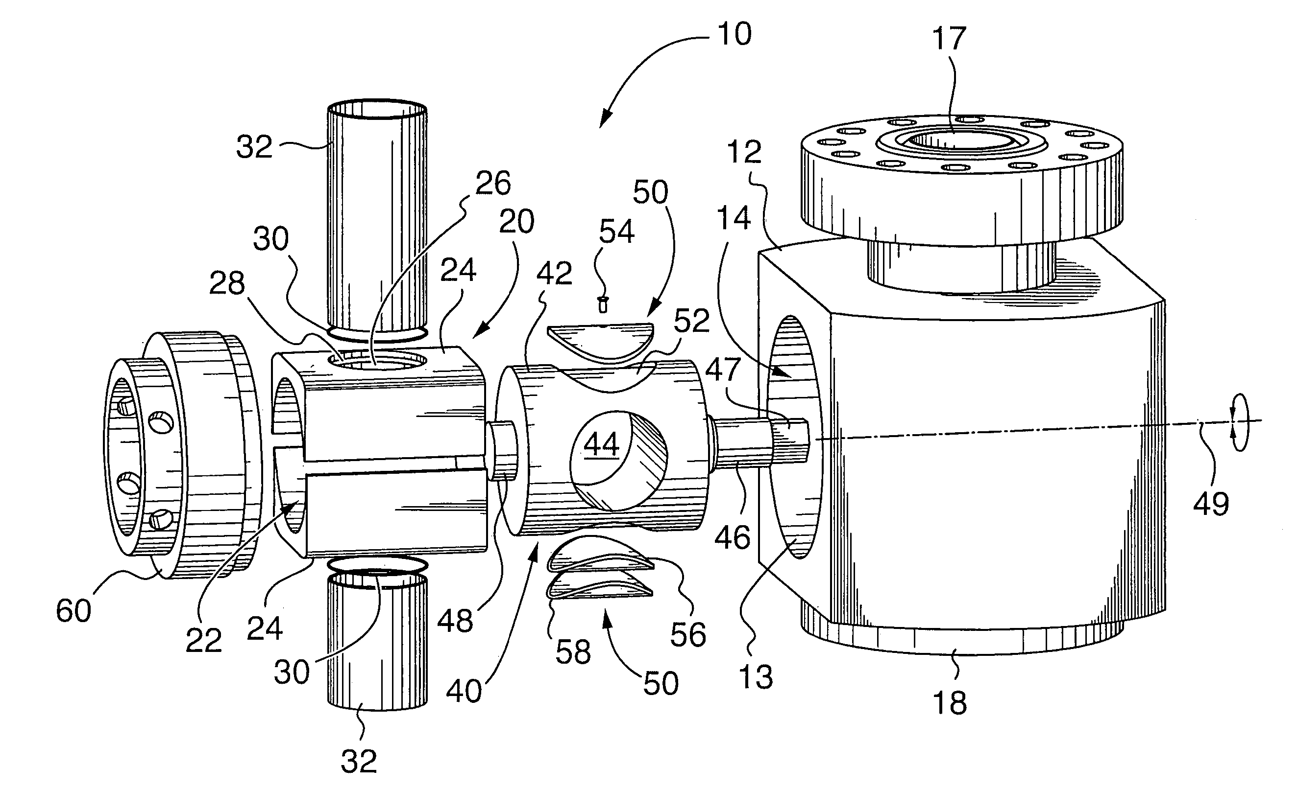
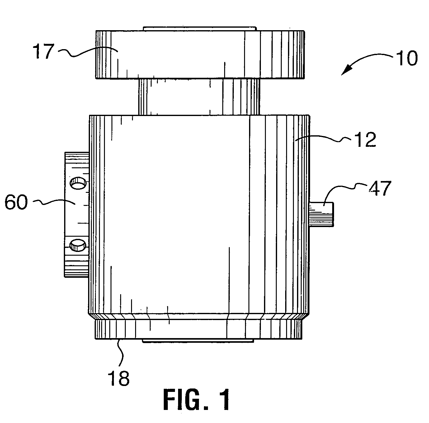
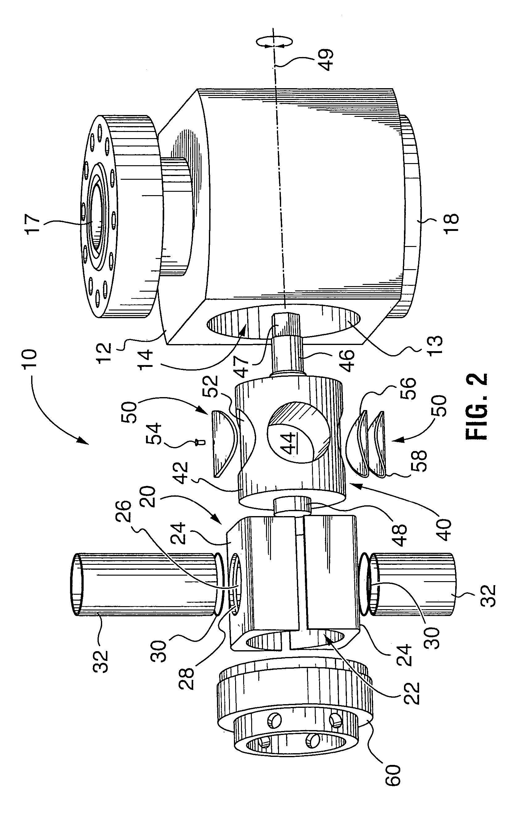
[0027]In general, and as will be explained in detail below, a plug valve in accordance with the invention includes a valve body, a cage fitted within the valve body and a rotatable plug housed within a cylindrical cavity in the cage. The plug can be rotated between an open position, in which fluid flows through the valve, and a closed position, in which fluid flow is obstructed. The cage has first and second opposed flat side surfaces, each side surface having a port for receiving a replaceable flow-path insert. In one embodiment, an annular sealing element, such as an elastomeric O-ring, provides a fluid-tight seal between the flow-path insert and the port. In another embodiment, the plug also includes at least one inset seal shaped to be substantially flush with the cylindrical surface of the plug. The inset seal has an outer surface of an elastomeric material for sealing at least one of the ports when the plug is in the closed position, thereby inhibiting leakage through the valv...


PUM

PropertyMeasurementUnit
Rockwell Hardnessaaaaaaaaaa
yield strengthaaaaaaaaaa
Rockwell Hardnessaaaaaaaaaa

Abstract

A plug valve has a valve body, a cage fitted within the valve body and a rotatable plug housed within a cylindrical cavity in the cage, for controlling fluid flow through the valve. The cage has first and second opposed flat side surfaces, each side surface has a port for receiving a replaceable flow-path insert in a fluid-tight seal. In one embodiment, the plug also includes at least one inset seal for sealing the at least one of the ports when the plug is in a closed position to inhibit leakage through the valve at low fluid pressures.

Description

CROSS-REFERENCE TO RELATED APPLICATIONS[0001]This is the first application filed for the present invention.MICROFICHE APPENDIX[0002]Not Applicable.TECHNICAL FIELD[0003]The present invention relates in general to high-pressure valves for the oil and gas industry and, in particular, to plug valves used in severe service applications in which flow path components, of the valve are subject to wear.BACKGROUND OF THE INVENTION[0004]Plug valves are used in the oil and gas industry for heating and treating systems, cementing, fracturing and acidizing and other well stimulation applications in which high working pressures and abrasive and / or corrosive fluids are conducted at high flow rates.[0005]Prior art plug valves are subject to wear. However, attempts have been made to permit at least some components in the flow path to be replaced. For example, U.S. Pat. No. 6,675,825 to Reeves et al., includes a valve body, an insert (or “cage”) fitted non-rotatably within the valve body and a plug ro...

Claims


Application Information

Patent Timeline
17 Apr 2007
Publication
US7204474B2
IPC
F16K5/00
CPC
F16K5/0407; F16K5/0478; F16K5/184; Y10T29/49407; Y10T29/49719; Y10T29/49721; Y10T29/49718; Y10T29/4973
Inventors
MCGUIRE, BOB; DALLAS, L. MURRAY