Axle supporting structure for industrial vehicle and industrial vehicle having the same

a technology for axles and industrial vehicles, applied in mechanical devices, transportation and packaging, tractors, etc., can solve the problems of increasing the cost of the prior art axle supporting structure, difficult to ensure that the insertion holes of the paired center pin are positioned in concentric relation to each other, and troublesome and costly problems, and achieve the effect of low cost and large strength

Inactive Publication Date: 2007-04-17
TOYOTA IND CORP
View PDF9 Cites 12 Cited by
  • Summary
  • Abstract
  • Description
  • Claims
  • Application Information

AI Technical Summary

Benefits of technology

[0008]The present invention is directed to an axle supporting structure which achieves a relatively large strength at a low cost and which rotatably supports a center pin of an axle beam between a pair of axle supporting units, and to an industrial vehicle having the axle supporting structure.

Problems solved by technology

In the reference, however, each upper axle supporting member of the axle supporting units is joined to the rear frame by welding which is troublesome and costly.
Further, in the prior art wherein each upper axle supporting member of the axle supporting units is joined to the rear frame by welding, it is difficult to ensure that the paired center pin insertion holes are positioned in concentric relation to each other.
However, since rubber is relatively costly, the cost of the prior art axle supporting structure is increased.
Further, in the prior art structure disclosed in the above reference, the strength at the joints between the upper axle supporting members and the rear frame is not sufficient.
That is, it is difficult to ensure a sufficiently high strength in the prior art axle supporting structure.

Method used


Image

  • Axle supporting structure for industrial vehicle and industrial vehicle having the same
  • Axle supporting structure for industrial vehicle and industrial vehicle having the same
  • Axle supporting structure for industrial vehicle and industrial vehicle having the same

Examples


Embodiment Construction

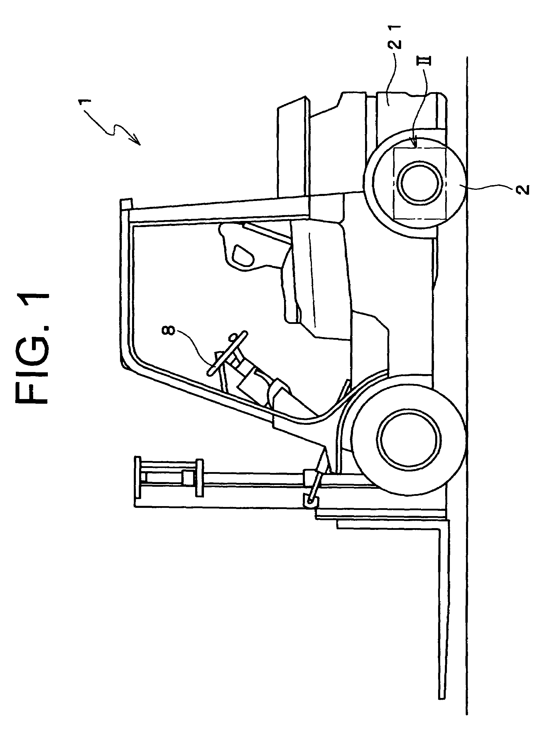
[0018]An axle supporting structure for an industrial vehicle according to a preferred embodiment of the present invention will be now described with reference to FIGS. 1 though 4. The following description of the present preferred embodiment will be made by way of a forklift truck as an example of the industrial vehicle.

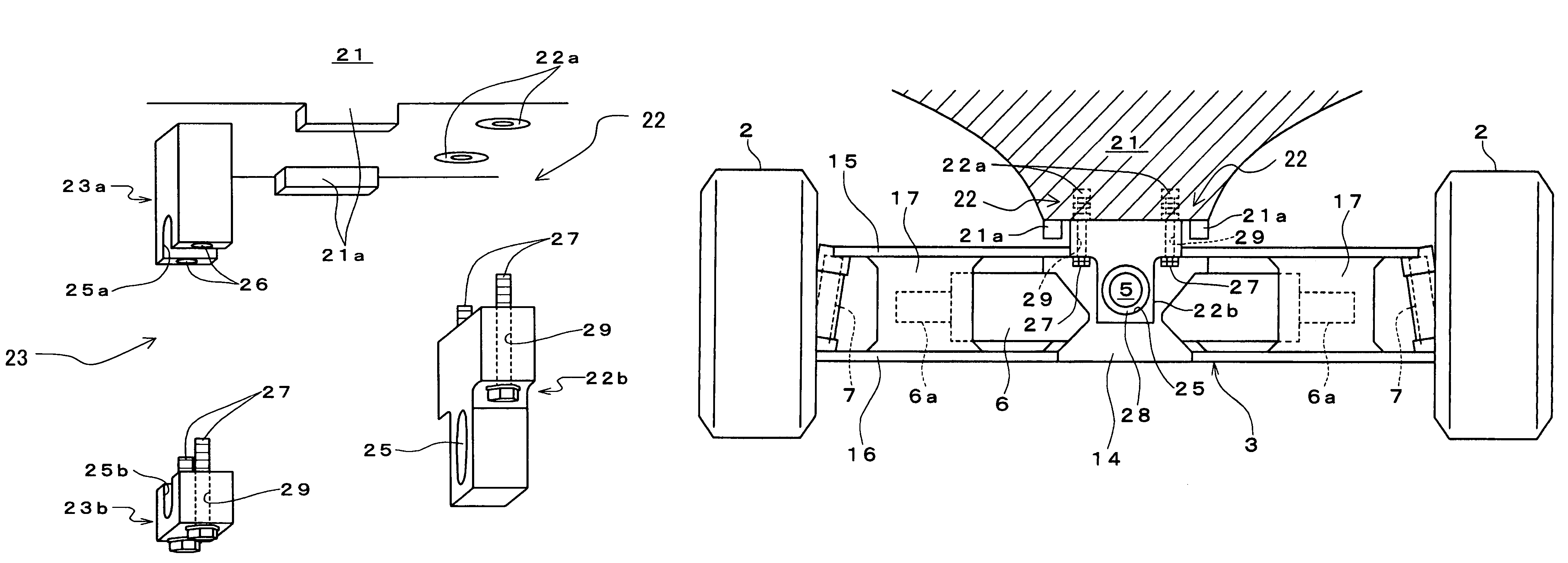
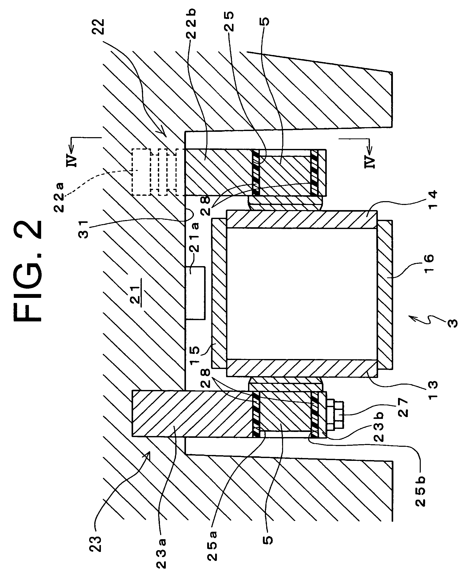
[0019]FIG. 1 is a side view illustrating a forklift truck 1 according to the preferred embodiment of the present invention. As show in FIG. 1, the forklift truck 1 includes a counterweight 21 in the rear of the vehicle. The counterweight 21 is made of a block of casting having an external shape adapted to form the rear part of vehicle and formed with recesses for accommodating therein rear axle wheels 2, a rear axle beam 3 which will be described in detail in later part hereof and axle supporting units which are shown in FIGS. 2 and 3. It is noted that FIG. 2 is a partially enlarged sectional view illustrating cross-section of the rear axle beam at the center along t...


PUM


Abstract

An axle supporting structure for supporting an axle beam for an industrial vehicle includes a center pin, a pair of axle supporting units and a counterweight. The center pin protrudes from the axle beam. Each axle supporting unit has formed therethrough an insertion hole in which the center pin is inserted. The axle supporting unit has an upper axle supporting member and a lower axle supporting member which is detachably connected to the upper axle supporting member. The pair of axle supporting units is spaced from each other in a traveling direction of the vehicle. The center pin is rotatably supported between the pair of axle supporting units. The upper axle supporting members of the axle supporting units are cast in the counterweight.

Description

BACKGROUND OF THE INVENTION[0001]The present invention relates to an axle supporting structure of an industrial vehicle which rotatably supports a center pin of an axle beam between a pair of axle supporting units which are spaced away from each other in a traveling direction of the industrial vehicle, and to the industrial vehicle having the same.[0002]In a counterbalanced forklift truck, its rear axle beam is generally supported in such a manner that the beam is pivotable or swingable in a rolling plane about a center pin for improving the stability of the vehicle when traveling on the surface of a rough ground. The center pin of the rear axle beam is inserted through holes formed in a pair of axle supporting units which are spaced away from each other and located at the front and rear sides of the rear axle beam, thus being rotatably supported by the pair of axle supporting units.[0003]The axle supporting units protrude downward from a rear frame that horizontally extends in the ...

Claims


Application Information

Patent Timeline
Patent Type & Authority Patents(United States)
IPC IPC(8): B62D49/08B60G1/02B60B35/14B60B35/16B60G9/02
CPCB60G9/02B60G2300/022B60G2200/322F16C11/045B60B35/14
Inventor MIYAKE, TAKAHITOKOBAYASHI, HIROSHIUEMATSU, SHUOMIURA, TOMOMICHIKATAE, KENICHI
Owner TOYOTA IND CORP
Why Eureka
Try Eureka