
Adjustable prescription lens insert for safety eyewear

a technology for eyewear and inserts, applied in the field of eyewear safety, can solve the problems of difficulty and inadequacies, excessive size, and inability to adjust the prescription lens insert, and achieve the effect of easy replacemen

Inactive Publication Date: 2007-04-17
NORTH SAFETY PRODS EURO
View PDF8 Cites 34 Cited by
  • Summary
  • Abstract
  • Description
  • Claims
  • Application Information

AI Technical Summary

Benefits of technology

"The invention is a new method for making a safety shield with prescription lenses. The new method allows for easy replacement of scratched or damaged lenses, and allows for individual positioning and angular orientation of each lens independently of the shield curvature. The new mount also allows for easy replacement of the insert frame and enclosed lenses. The safety shield includes a transparent shield and a prescription lens insert with adjustable position and orientation of the lenses. The insert has eye wires and upper and lower arms connected to the eye wires, which hold the lens. The insert is attached to the shield using a central bridge and bendable arms. The technical effects of the invention include easy replacement of lenses, adjustable position and orientation of lenses, and improved safety and comfort for wearers."

Problems solved by technology

However, use of these products by persons who wear prescription eyeglasses, often leads to problems.
Most safety eyewear does not fit well or does not fit at all over basic eyeglasses.
Where it might fit well, it would be excessively large.
While the concept of mounting prescription lenses in an eye shield is basically simple, there have been difficulties and inadequacies with the results.
A principal problem has been lack of adjustability, namely the inability to achieve the same full adjustability of lenses in a safety shield that an optician could achieve with a basic eyeglass frame.
In eye shields of contemporary design and style, the shield curvature is typically greater than the curvature that occurs in an eyeglass frame, and consequently, lenses mounted on the interior surface at the shield curvature can create optical distortion for the wearer.
In summary, the current safety eyewear has problems and disadvantages pertaining to the inability to fully adjust prescription lenses after they are inserted in the mounting frame, and the cost and difficulty to replace prescription lenses in safety eyewear.

Method used


Image

  • Adjustable prescription lens insert for safety eyewear
  • Adjustable prescription lens insert for safety eyewear
  • Adjustable prescription lens insert for safety eyewear

Examples


Embodiment Construction

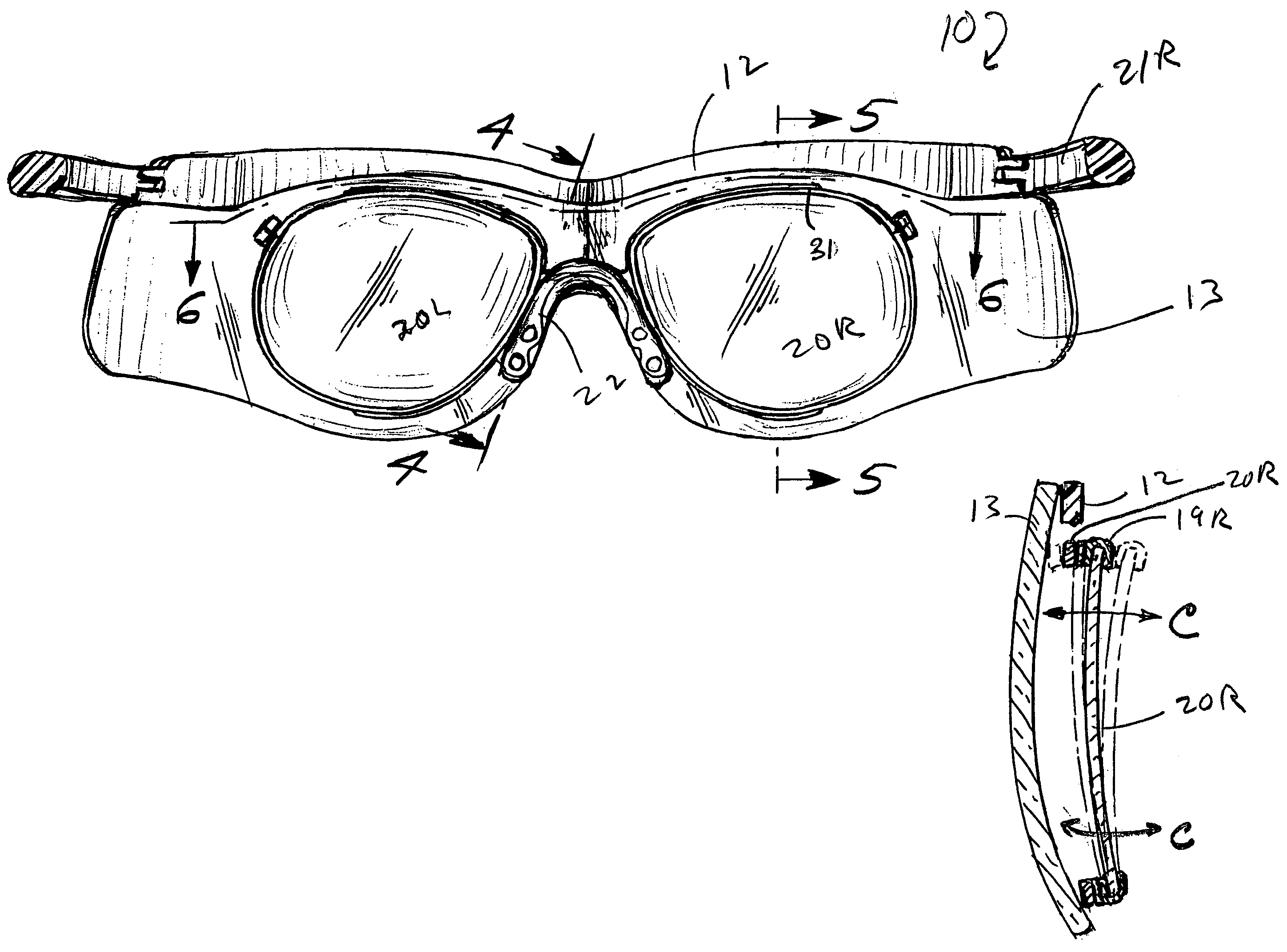
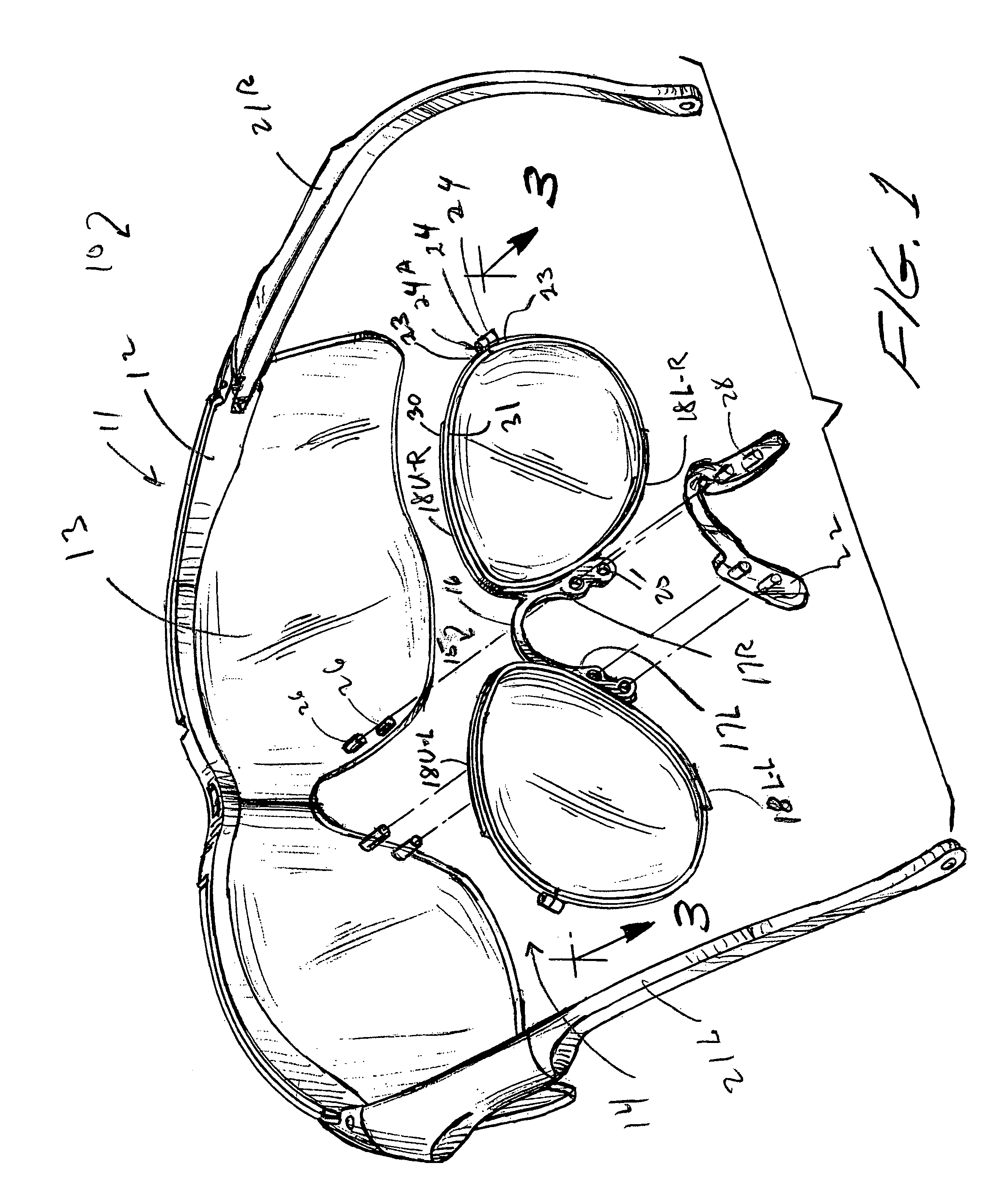
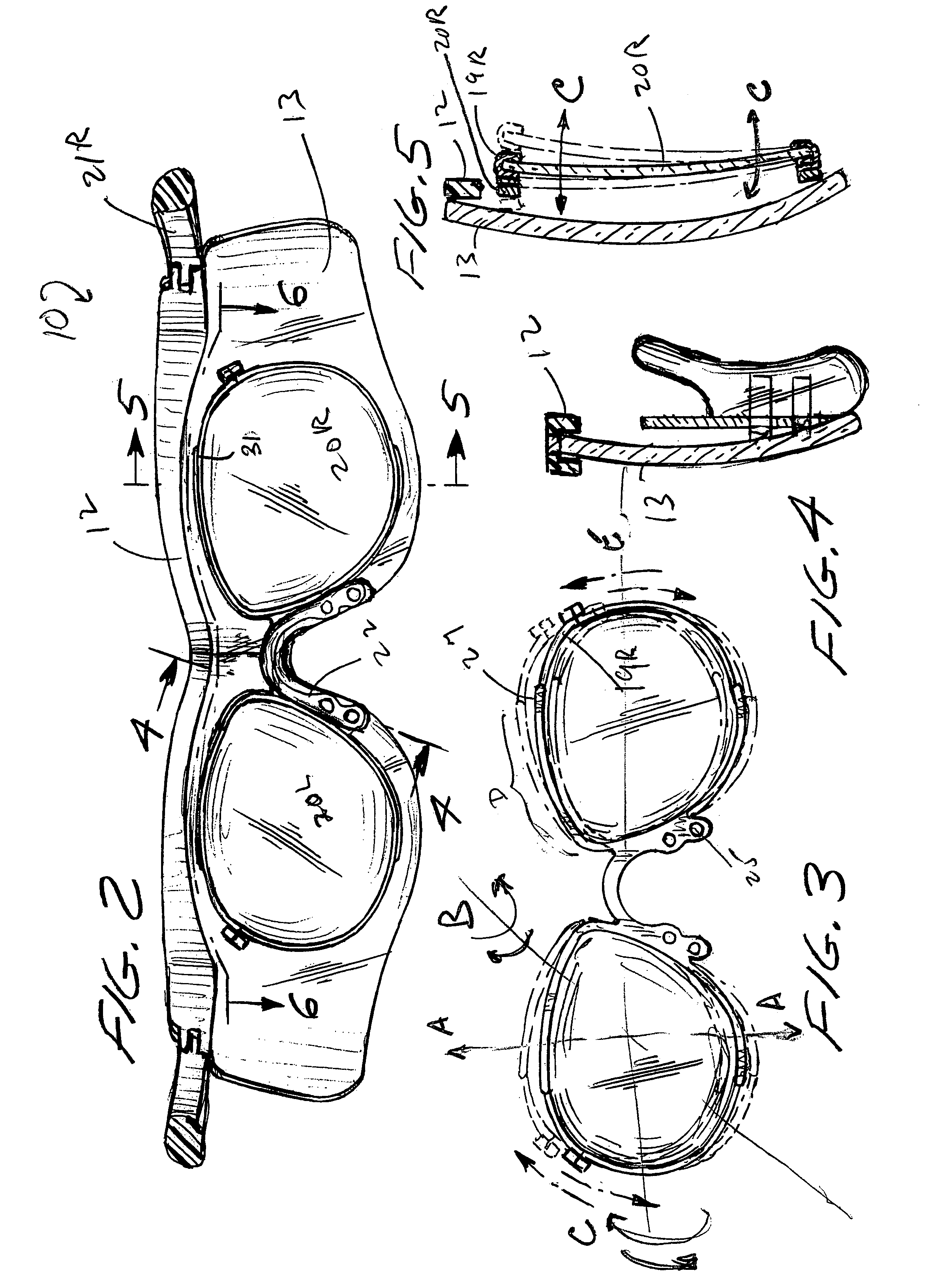
[0044]A first embodiment of the new safety eyewear 10 as seen in FIGS. 1–8, comprises:[0045]a. a safety shield sub-assembly 11 comprising frame 12 and transparent optical shield 13 secured to frame 12;[0046]b. a prescription lens insert subassembly 14 comprising: (1) bridge 15 having central part 16 with opposite sides 17L, 17R, (2) a set of upper and lower arms extending from each of said sides 17L, 17R respectively, these arms being designated 18U-L for upper left, 18 L-L for lower left, 18U-R for upper right and 18L-R for lower right, and (3) eyewires 19L, 19R, each surrounding and holding a prescription lens 20R, 20L. The left and right sides of the shield, the insert and the lenses are substantially the same, but one being the mirror image of the other. Thus, the description of one side will suffice for both;[0047]c. temples or earpieces 21L, 21R extending from opposite ends of frame 12; and[0048]d. nose piece 22 secured to bridge 15.

[0049]The novelty of the present structure i...


PUM


Abstract

A protective eyewear article including:a. a transparent shield formed as a curved panel including a central nose area, the shield adapted for placement on a wearer's face.b. a prescription lens insert adapted to be attached to the shield, to releasably hold prescription lenses and to allow adjustment of position and orientation of the lenses in relation to the shield, the insert comprising:(i) a set of eye wires, each defining a closed loop having top and bottom parts, each loop adapted to circumscribe and hold the edges of a lens,(ii) a central bridge portion having opposite sides, and(iii) a set of upper and lower arms extending outward from each of the sides of the central bridge portion, the upper and lower arms of each set having proximal ends fixed to one of the sides of the central bridge portion and distal ends fixed to the top and bottom parts of one of the eye wires, respectively, andc. means for connecting the central bridge portion of the insert to the corresponding central nose area of the shield,d. the arms being bendable for adjusting the position and orientation of the lenses relative to the shield.

Description

A. FIELD OF THE INVENTION[0001]This invention is in the field of safety eyewear, such as safety eye shields and masks, and particularly eye shields on which prescription optical lenses can be mounted.B. BACKGROUND OF THE INVENTION[0002]Protective eyewear is highly useful in many industrial, sports and leisure activities, and in numerous of these activities use of protective eyewear is mandatory under industrial and / or governmental regulations. A partial listing of situations where use of protective eyewear is now common includes, but is not limited to, environments where there is dust, pollution and sparks, flying fragments of various sizes, high wind, and in chemical laboratories, welding, machining and assembly areas, and essentially in any environment where any foreign substance or particle could move into contact with the eye. Exemplary areas of protective eyewear use in sports and leisure fields, include skiing, bicycling, flying, vehicle racing of all types, water sports, skyd...

Claims


Application Information

Patent Timeline
Patent Type & Authority Patents(United States)
IPC IPC(8): G02C9/00
CPCG02C9/00
Inventor PIETERMAN, JAN-JOOST
Owner NORTH SAFETY PRODS EURO
Learn More