Illumination apparatus

a technology of illumination apparatus and back, which is applied in the direction of mechanical apparatus, lighting and heating apparatus, instruments, etc., can solve the problems of uneven brightness, inability to avoid uneven brightness, and point light sources that cannot be converted into uniform plane light sources, etc., and achieves low cost and satisfactory workability.

Inactive Publication Date: 2007-04-17
SEMICON ENERGY LAB CO LTD
View PDF23 Cites 10 Cited by
  • Summary
  • Abstract
  • Description
  • Claims
  • Application Information

AI Technical Summary

Benefits of technology

[0020]In accordance with the present invention, a point light source is converted into a line light source by means of a linear light guiding plate, and further into a plane light source by means of a plane-like light guiding plate. Thus, the plane light source having less unevenness in the brightness can be formed even when a point light source is employed.
[0039]Although the light emitting diode has been described as the point light source, application of the present invention is not limited to the light emitting diode. The present invention can be widely employed as means for converting a point light source into a plane light source. The plate-like light guiding plate in accordance with the present invention may have a shape such as a rectangular parallelepiped which has satisfactory workability. Thus, a back light can be produced at a low cost.

Problems solved by technology

However, when the cold cathode fluorescent tube is used as the light source, most of power consumption of the liquid crystal display device is derived from the back light or the front light.
In an attempt where a point light source such as a light emitting diode is converted into a plane light source so as to obtain a uniform lightness in a large area, unevenness in the brightness cannot be avoided.
However, even when a plurality of point light sources are disposed on the side surface of the plate-like light guiding plate, these point light sources can not be converted into a uniform plane light source.
With a large unevenness in the brightness, the visibility is significantly damaged.

Method used


Image

  • Illumination apparatus
  • Illumination apparatus
  • Illumination apparatus

Examples


embodiment mode 1

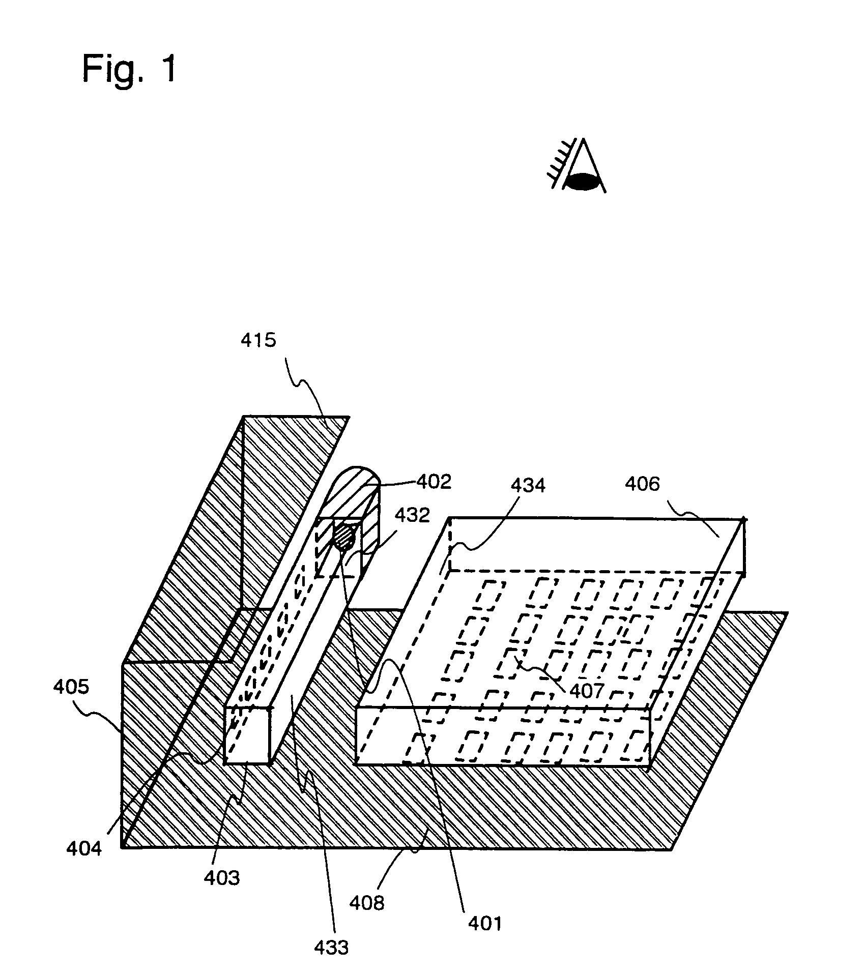
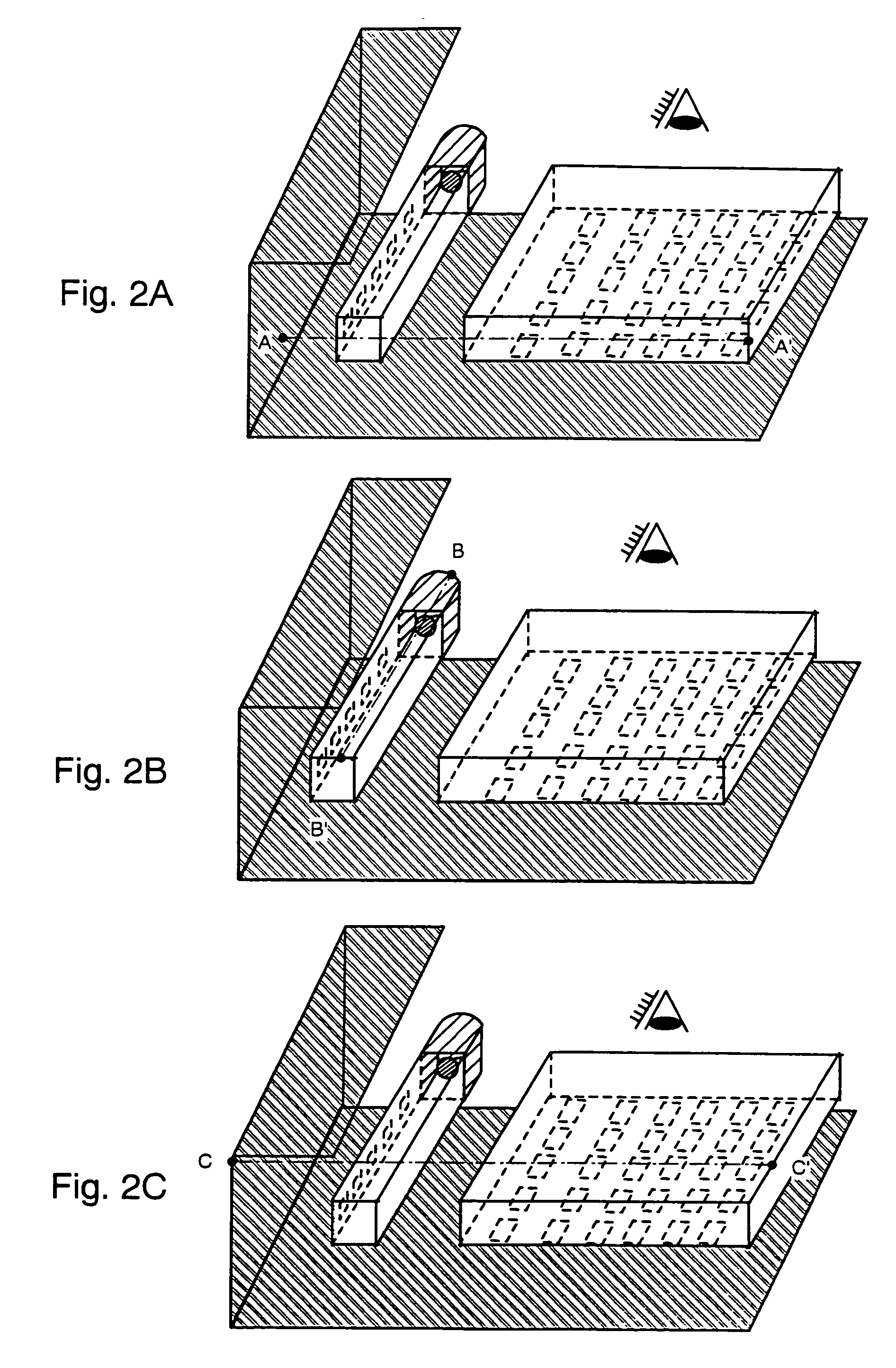
[0075]In Embodiment Mode 1, the present invention will be applied to a back light of a transmission type liquid crystal electro-optical device. Embodiment Mode 1 will be described with reference to FIG. 1.

[0076]In order to explain Embodiment Mode 1, six surfaces of the light guiding plate are defined as shown in a perspective view of FIG. 19A. More specifically, a surface closer to a viewer is referred to as an upper surface 735. A surface opposite to the upper surface is referred to as a lower surface 736. A surface on which the light emitted from a light source 737 is referred to as an end surface 738. Surfaces perpendicular to the end surface are referred to as side surfaces 739. The other side surface is referred to as a surface 740 parallel to the end surface. The following descriptions with reference to FIG. 1 are based on the above definitions.

[0077]A light emitting diode 401 is disposed on a first end surface 432 of a linear light guiding plate (first light guiding plate) 40...

embodiment mode 2

[0092]The present embodiment mode describes an example in which the present invention is applied to a front light of a reflection type liquid crystal electro-optical device. The embodiment mode is characterized in that a point light source by means of a light emitting diode is converted into a line light source by a linear light guiding plate.

[0093]In order to explain Embodiment Mode 2, six surfaces of the light guiding plate are defined as shown in a perspective view of FIG. 19A. More specifically, a surface closer to a viewer is referred to as an upper surface 735. A surface opposite to the upper surface is referred to as a lower surface 736. A surface on which the light emitted from a light source 737 is specifically referred to as an end surface 738. Surfaces perpendicular to the end surface are referred to as side surfaces 739. The other side surface is referred to as a surface 740 parallel to the end surface. The following descriptions with reference to FIGS. 4, 5A and 5B, 6, ...

embodiment mode 3

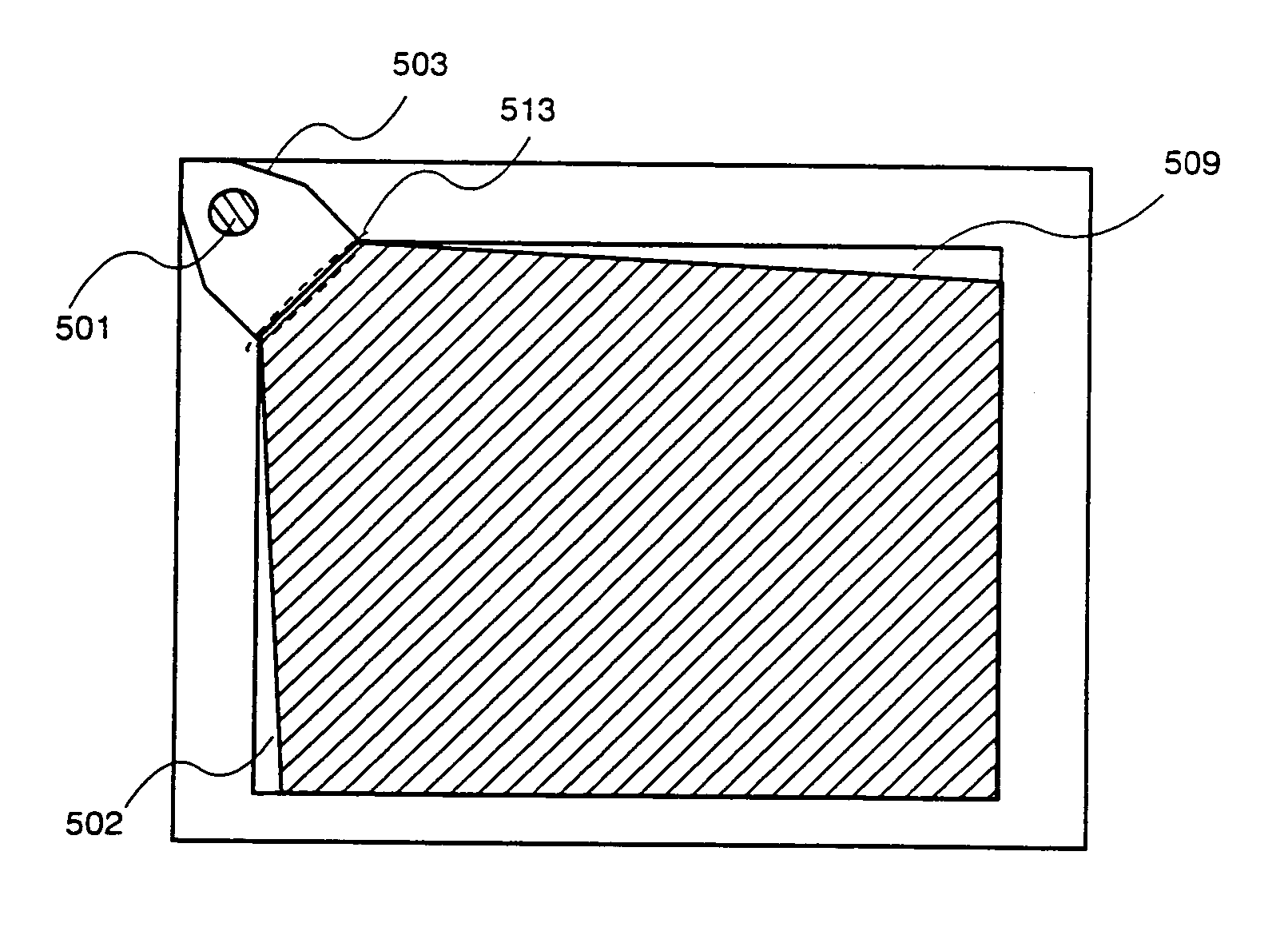
[0099]The present invention will be described in Embodiment Mode 3. The present embodiment mode is characterized by the shape of the plate-like light guiding plate. More specifically, in the present embodiment mode, the first side surface of the plate-like light guiding plate on which the light is to be incident is configured to have an angle of 45° with respect to the other side surfaces of the plate-like light guiding plate. The point light source such as a light emitting diode is disposed in front of the first side surface.

[0100]In order to explain Embodiment Mode 3, surfaces of the plate-like light guiding plate are defined as shown in a perspective view of FIG. 19B. More specifically, a surface closer to a viewer is referred to as an upper surface 741. A surface opposite to the upper surface is referred to as a lower surface 742. The remaining surfaces are referred to as side surfaces 743. The following descriptions with reference to FIGS. 10, 11A, and 11B are based on the abov...


PUM


Abstract

A point light source is converted into a plane light source having a satisfactory uniformity. The point light source is converted into a line light source by means of a linear light guiding plate, and further into the plane light source by means of a plane-like light guiding plate. Light from the point light source is reflected at a lamp reflector to be incident on at least two side surfaces of the plane-like light guiding plate.

Description

CROSS-REFERENCE TO RELATED APPLICATIONS[0001]This application is a continuation application of U.S. application Ser. No. 09 / 833,397 filed Apr. 11, 2001 now U.S. Pat. No. 6,789,910 now allowed, which, under 35 USC 119, claims the benefit of a foreign priority application filed in Japan as Serial No. 2000-111345 on Apr. 12, 2000. This application claims priority to each of the prior applications, and the disclosures of the prior applications are considered part of (and are incorporated by reference in) the disclosure of this application.BACKGROUND OF THE INVENTION[0002]1. Field of the Invention[0003]The present invention relates to an illumination apparatus for illuminating an image display plane of a liquid crystal display device, and more specifically, relates to a scheme intended to realize a uniform in-plane brightness of the illumination apparatus in a method for converting a point light source into a plane light source. By means of the present invention, an illumination apparatu...

Claims


Application Information

Patent Timeline
Patent Type & Authority Patents(United States)
IPC IPC(8): F21V7/04F21V8/00
CPCG02B6/0028G02B6/0031G02B6/0038G02B6/0043G02F1/1336G02B6/0055H01L29/786G02B6/0046G02F1/133615
Inventor KIMURA, HAJIMESATAKE, RUMO
Owner SEMICON ENERGY LAB CO LTD
Why Eureka
Try Eureka