Coaxial connector

a technology of coaxial connectors and connectors, applied in the direction of coupling devices, two-part coupling devices, electrical apparatus, etc., can solve the problems of deterioration of vswr, inability to maintain the matching of characteristic impedances, and poor frequency characteristic, so as to improve vswr and excellent frequency characteristic

Inactive Publication Date: 2007-04-17
JST MFG CO LTD
View PDF9 Cites 10 Cited by
  • Summary
  • Abstract
  • Description
  • Claims
  • Application Information

AI Technical Summary

Benefits of technology

[0011]It is an object of the present invention to provide a coaxial connector excellent in frequency characteristic that, even when a high frequency signal of gigahertz-class is transmitted through a coaxial cable, the characteristic impedance of the coaxial cable can be maintained thus enabling to improve the VSWR.
[0015]In any one of the above aspects, adjustment is made such that, when connecting the connector, the characteristic impedance of the coaxial cable becomes a predetermined value. Accordingly, even where a high frequency signal of gigahertz-class is transmitted through the coaxial cable, the characteristic impedance of the coaxial cable can be maintained thus enabling to improve the VSWR.

Problems solved by technology

Where using a coaxial cable, there arises a problem of matching between the characteristic impedances of the coaxial cable and of an object connected to the cable.
In this state, in the case a high frequency signal at several gigahertz is transmitted through the coaxial cable, matching of characteristic impedances cannot be maintained, and VSWR deteriorates.
Due to this, the characteristic impedance of the coaxial cable cannot to be maintained, and thereby the VSWR deteriorates.

Method used


Image

  • Coaxial connector
  • Coaxial connector
  • Coaxial connector

Examples


Embodiment Construction

[0030]In the following, a coaxial connector in one preferred embodiment of the present invention will be explained with reference to the accompanying drawings.

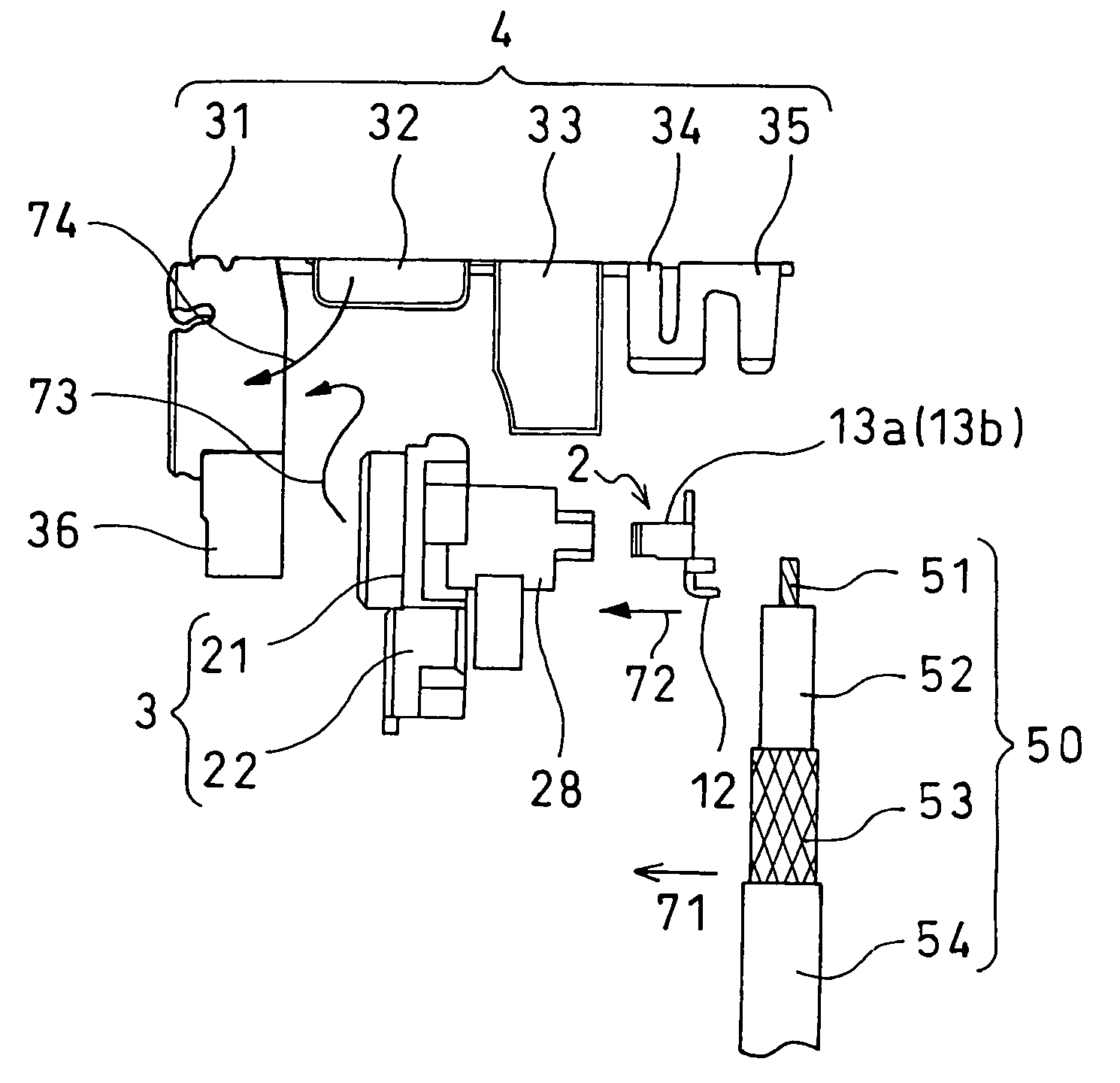
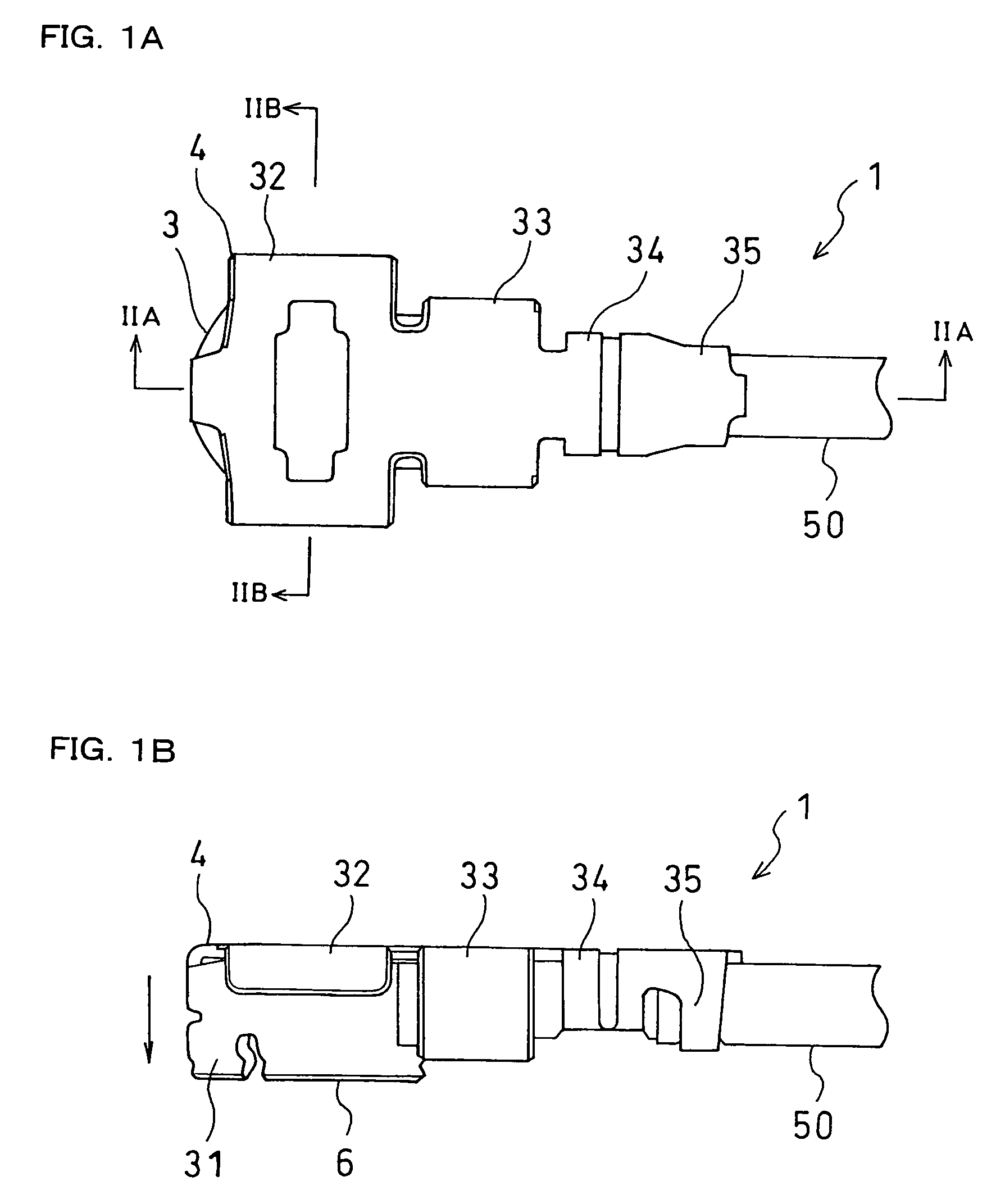
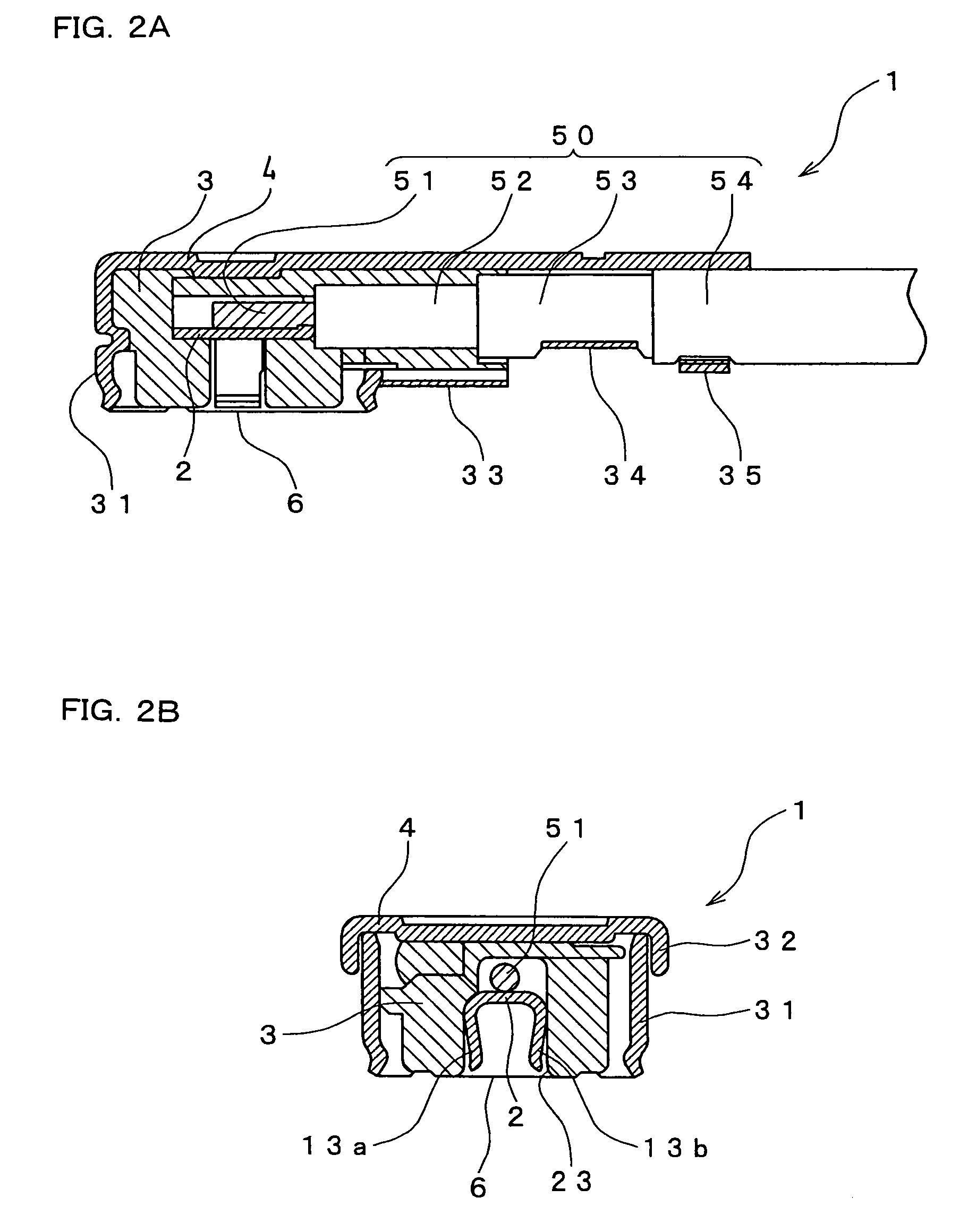
[0031]FIGS. 1A and 1B are exterior views of a coaxial connector 1 connected with a coaxial cable 50. FIG. 1A is a top view of the coaxial connector 1, while FIG. 1B is a left side view of the coaxial connector 1. The arrow in FIG. 1B represents the direction in which the coaxial connector 1 is connected to another connector (not shown). FIGS. 2A and 2B are views showing a sectional structure of the coaxial connector 1. FIG. 2A is a sectional view of the coaxial connector 1 on line IIA—IIA shown in FIG. 1A, while FIG. 2B is a sectional view of the coaxial connector on line IIB—IIB shown in FIG. 1A.

[0032]As shown in FIGS. 1a, 1B, 2A and 2B, the coaxial connector 1 has a contact 2, a housing 3, and a shell 4. The coaxial connector 1 also has a connection 6 at its underside (at the lower side in FIG. 1B), for connection with the o...


PUM


Abstract

A coaxial connector comprises a contact electrically connected with a core of a coaxial cable, a shell electrically connected with a shield of the cable, and a housing that supports the contact and insulates the contact from the shell. The capacitance between the portion consisting of the contact and the part of the core connected thereto together with an insulator exposed out of the shield, and the shell, is adjusted by a capacitance adjustment plate so that the coaxial cable has characteristic impedance of a predetermined value.

Description

BACKGROUND OF THE INVENTION[0001]1. Field of the Invention[0002]The present invention relates to a coaxial connector to be connected with a coaxial cable.[0003]2. Description of the Related Art[0004]Where using a coaxial cable, there arises a problem of matching between the characteristic impedances of the coaxial cable and of an object connected to the cable. If the characteristic impedances do not match, a reflection wave occurs at the connection point of the coaxial cable, deteriorating the VSWR (voltage standing wave ratio). Accordingly, it is a practice to use a coaxial cable having characteristic impedance appropriate for an object being connected thereto. For a coaxial connector to be connected with such a coaxial cable, there is known a technology for reducing the size and cost by making innovative changes in the shape thereof (see Japanese published unexamined application No.2002-164132).[0005]In order to connect a coaxial connector with a coaxial cable, a core as an inner ...

Claims


Application Information

Patent Timeline
Patent Type & Authority Patents(United States)
IPC IPC(8): H01R9/05H01R24/44H01R13/658
CPCH01R24/44H01R9/0518H01R2103/00
Inventor KUKITA, HIROAKI
Owner JST MFG CO LTD
Why Eureka
Try Eureka