Membrane for key switch and the key switch

a key switch and membrane technology, applied in the field of key switches, can solve problems such as switch malfunction, and achieve the effect of avoiding contact failure of the key switch

Inactive Publication Date: 2007-04-17
THE FUJIKURA CABLE WORKS LTD
View PDF19 Cites 6 Cited by
  • Summary
  • Abstract
  • Description
  • Claims
  • Application Information

AI Technical Summary

Benefits of technology

[0013]In the case of the key switch 200, an area of the contact 104A which contacts with the wiring pattern 4 of the base plate 6 is smaller than that of the contact 104 of the key switch 100. Thus, even if dust such as glass floss enters the surrounded space, the contact failure of the key switch 200 is less likely to occur as compared with the key switch 100.
[0014]The key switch 300 includes the plurality of contacts 104. When the key switch 300 is pressed, if at least one of the contacts comes into contact with the wiring pattern 4 of the base plate 6, the contact failure of the key switch can be avoided. Thus, the contact failure is further less likely to occur as compared with the key switch 200.
[0020]When the key switch 400 is pressed, the edge portion of the base plate 6 on the side of the outer peripheral edge forms a contact 104B, and this contact 104B and the wiring pattern 4 of the base plate 6 are brought into contact with each other and are electrically connected. In the key switch 400, the edge of the through hole 102E formed in substantially central portion of the key switch diaphragm 102D forms the contact 104B. Thus, when the key switch 400 is pressed, even if dust exists in the surrounded space, the contact 104B easily contacts with the wiring pattern 4 of the base plate 6, and the contact failure can be avoided. Since there exists no raised portion on the recessed side of the key switch diaphragm 102D, the pressing stroke can be ensured, and a good click feeling can be obtained, without increasing the height of the truncated pedestal 16.
[0026]The present invention has been achieved in view of the above problems, and the present invention provides a key switch diaphragm and a key switch having a high durability and capable of obtaining a good click feeling when the switch is pressed, and capable of avoiding generation of contact failure.

Problems solved by technology

There is also a problem that a switching malfunction occurs due to contact failure of the key switch 100 in some cases.

Method used


Image

  • Membrane for key switch and the key switch
  • Membrane for key switch and the key switch
  • Membrane for key switch and the key switch

Examples


first embodiment

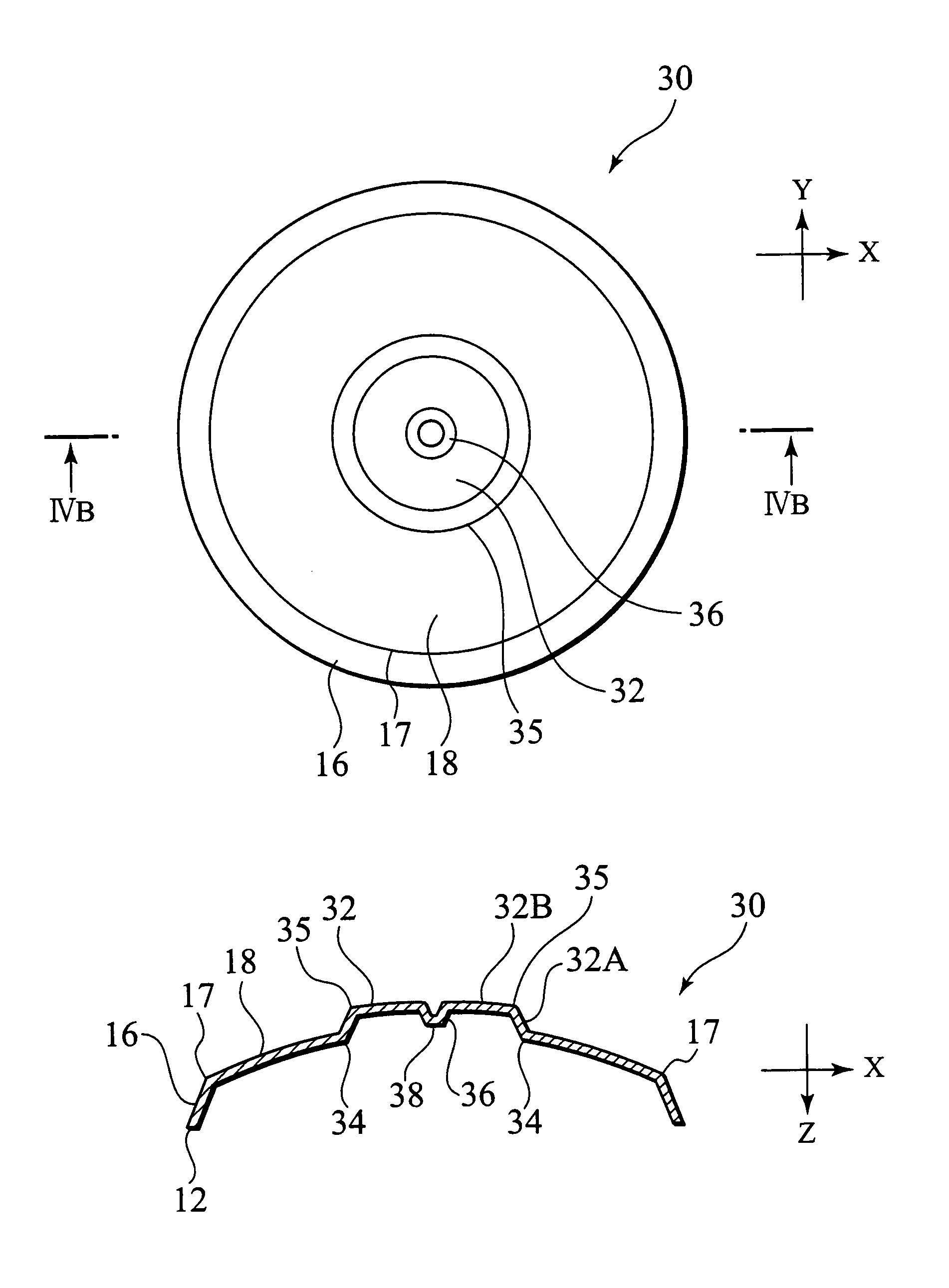
[0042]FIGS. 4A and 4B show an outline structure of a key switch diaphragm 30 constituting a key switch 1 according to a first embodiment of the present invention. FIG. 4A is a plan view of the key switch diaphragm 30, FIG. 4B is a sectional view taken along the line IV B—IV B in FIG. 4A. FIG. 5 shows a state where the key switch 1 constituted by the key switch diaphragm 30 is pressed. In FIG. 4A, a base plate 6, a cover film 10 and a wiring pattern 2, 4 of the base plate 6 are omitted to facilitate understanding.

[0043]The key switch diaphragm 30 is integrally formed by pressing a thin plate (e.g., metal thin plate) having flexibility and conductivity. The key switch diaphragm 30 is formed such that the key switch diaphragm 30 is squeezed toward a substantially central portion of a spherical domical portion 18, and an outwardly raised portion 32 being raised toward an upper side (raised side) of the domical portion 18 is formed. That is, the key switch diaphragm 30 includes the spher...

second embodiment

[0059]FIGS. 6(A) and 6(B) show an outline structure of a key switch diaphragm 40 constituting a key switch according to a second embodiment of the present invention. In the key switch diaphragm 40, the domical portion 32B of the outwardly raised portion 32 is provide at its substantially central portion with an outwardly raised portion 42, instead of the raised portion 36 of the first embodiment provided at the substantially central portion of the domical portion 32B of the outwardly raised portion 32. Other elements of the key switch diaphragm 40 are structured substantially the same as that of the key switch diaphragm 30.

[0060]That is, the key switch diaphragm 40 includes the outwardly raised portion 42 provided at the substantially central portion of the domical portion 32B of the outwardly raised portion 32. An inner surface side (recessed side) edge of the domical portion 32B functions as a contact 44. The outwardly raised portion 42 is raised such as to separate from the refer...

third embodiment

[0064]FIGS. 7(A) and 7(B) show an outline structure of a key switch diaphragm 50 constituting a key switch according to a third embodiment of the present invention. The key switch diaphragm 50 is different from the key switch diaphragm 30 of the first embodiment in that the substantially central portion of the domical portion 32B of the outwardly raised portion 32 is provided with a through hole 52 instead of the raised portion 36. Other elements of the key switch diaphragm 40 are structured substantially the same as that of the key switch diaphragm 30. In other words, the outwardly raised portion 32 is provided at its substantially central portion with the through hole 52. A contact 58 is formed on an edge of an inner surface side (on the side of the pedestal 16) of the through hole 52.

[0065]If the substantially central portion of the key switch constituted by the key switch diaphragm 50 is pressed, the key switch diaphragm 50 is elastically deformed, and the contact 34 of the key ...


PUM


Abstract

The present invention provides a key switch diaphragm capable of obtaining a good click feeling and capable of avoiding contact failure and having a high durability. A key switch diaphragm 30 comprises a thin plate having flexibility and conductivity, and the key switch diaphragm 30 includes a truncated pedestal 16, and a spherical domical portion 18 being raised toward an upper portion of the pedestal 16 on the side of the upper portion of the pedestal 16. The domical portion 18 is provided at its substantially central portion with an outwardly raised portion 32 being raised toward an outer surface of the domical portion 18. An edge of the outwardly raised portion 32 on the side of its inner surface forms a contact 34.

Description

TECHNICAL FIELD[0001]The present invention relates to a key switch (flat switch) having a conical pedestal and a spherical domical portion on an upper end of the pedestal, and the invention also relates to a key switch.BACKGROUND ART[0002]FIGS. 1A and 1B show an outline structure of a first conventional key switch 100. FIG. 1A is a plan view of the key switch 100, and FIG. 1B is a sectional view taken along the line IB—IB in FIG. 1A. FIG. 2 is a diagram showing a state where the key switch 100 is pressed. For example, the conventional key switch 100 used for a push button of a portable phone includes a base plate 6 provided with an annular wiring pattern 2, and with a wiring pattern 4 which is disposed on substantially a central portion of the wiring pattern 2 and which is separated from the wiring pattern 2. The key switch 100 also includes a key switch diaphragm 102 which is curved in a direction in which the central portion is separated away from the base plate 6 and which is dis...

Claims


Application Information

Patent Timeline
Patent Type & Authority Patents(United States)
IPC IPC(8): H01H9/26H01H13/48H01H13/702
CPCH01H13/702H01H13/48H01H2215/036H01H2205/018H01H2203/054
Inventor KAIZU, MASAHIROOMINATO, TADANORIHIRAI, KOJI
Owner THE FUJIKURA CABLE WORKS LTD
Why Eureka
Try Eureka