Connector

a technology of connecting rods and connectors, applied in the field of connecting rods, can solve the problems of general time and effort for manufacturing, and the cost tends to be high, and achieve the effect of low cost and space saving

Active Publication Date: 2017-11-14
AUTONETWORKS TECH LTD +2
View PDF15 Cites 6 Cited by
  • Summary
  • Abstract
  • Description
  • Claims
  • Application Information

AI Technical Summary

Benefits of technology

[0009]Vibration that would otherwise be transmitted from the core of the coated wire to the terminal fitting is blocked in a part where the core fixing portion integrated with the core is fixed to the housing and, hence, a contact failure between terminal fittings can be prevented. The part functioning to block the vibration is formed by embedding the core fixing portion provided on the core in the housing by molding, which can simplify a manufacturing process and contribute to a cost reduction.
[0012]No metal member is used in forming the core fixing portion. Thus, these configurations can contribute to a reduction in the number of components.
[0016]The flexible conductor functions to absorb an assembling tolerance of housings and the like. Since this flexible conductor is formed utilizing the core pulled out from the end of the coated wire, a structure can be simplified.
[0018]The connector is formed into an L shape, which can contribute to space saving in the fitting direction.
[0019]According to the technique disclosed by this specification, it is possible to provide a vibration blocking structure capable of blocking vibration at low cost.

Problems solved by technology

Thus, it generally takes time and effort for manufacturing and cost tends to be high.

Method used


Image

  • Connector
  • Connector
  • Connector

Examples


first embodiment

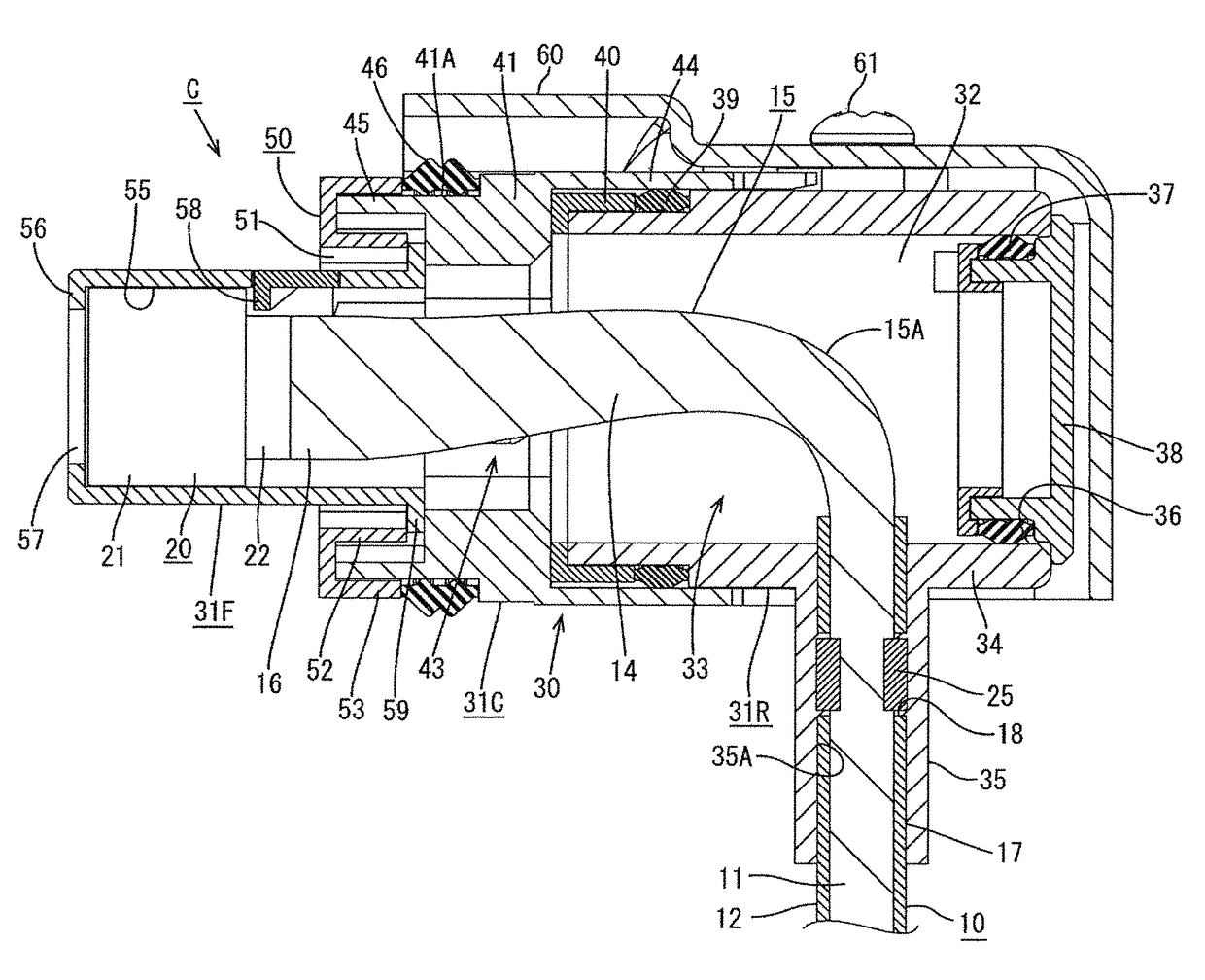
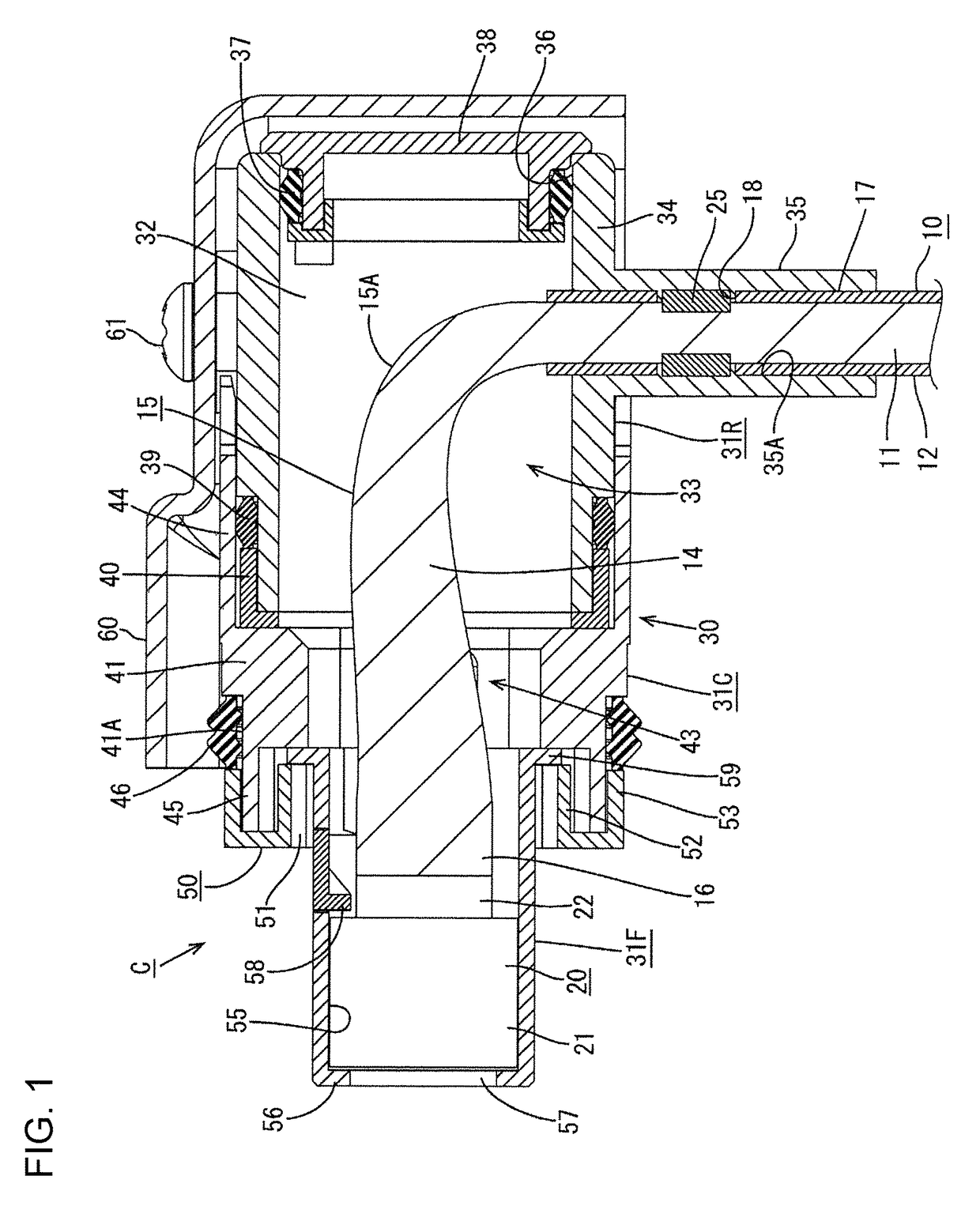
[0022]A first embodiment is described on the basis of FIG. 1. A connector C of this embodiment is used by being mounted on a case of a device (e.g. an inverter, a motor or the like installed in a hybrid vehicle or an electric vehicle).

[0023]The connector C roughly includes a plurality of terminal fittings 20 individually provided on ends of coated wires 10, a housing 30 made of synthetic resin and configured to accommodate the terminal fittings 20, and a shield shell 60 to be mounted to cover the housing 30.

[0024]The terminal fitting 20 is a female terminal and functions to be fit and connected to an unillustrated mating terminal (male terminal) mounted in a mating connector provided in the case. The terminal fitting 20 includes a terminal body 21 in the form of a rectangular tube having a resilient contact piece inside and a mounting plate 22 formed to extend from the rear edge of the terminal body 21.

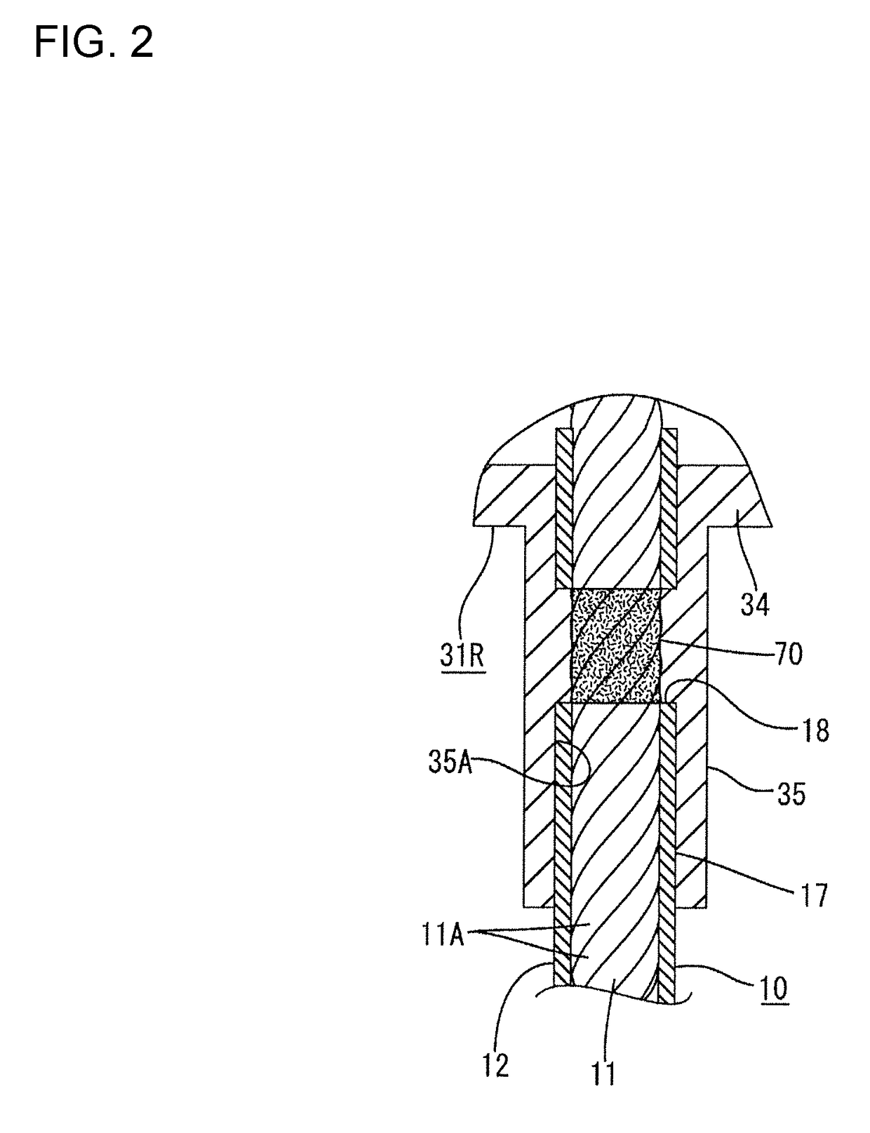
[0025]The coated wire 10 is structured such that an outer periphery of a core 11 ...

second embodiment

[0064]In light of the second embodiment, a core fixing portion may be formed by bonding the strands of the core projecting and exposed from the end of the coated wire at least on a base end side by resistance welding or ultrasonic welding, whereas a projecting end of the core may be connected to the end part of the L-shaped braided wire connected to the rear end of the terminal fitting, and the core fixing portion provided on a base end part of the exposed core may be embedded in the housing by molding as the vibration blocking structure.

[0065]Although the connector formed such that the wires are pulled in a right-angle direction from the rear surface of the housing is illustrated in the above embodiments, the present invention can be similarly applied to connectors formed such that wires are pulled out straight rearwardly of the housing.

[0066]Although the shield connector to be mounted on the case of an inverter or a motor is illustrated in the above embodiments, the present invent...


PUM


Abstract

A connector C to be mounted on a case of a device includes a coated wire 10 formed such that a core 11 is coated with an insulation coating 12, a terminal fitting 20 to be fit and connected to a mating terminal, a flexible conductor 15 interposed between the terminal fitting 20 and an end of the coated wire 10, and a housing 30 made of synthetic resin and accommodating the terminal fitting 20 together with the flexible conductor 15. The core 11 of the coated wire 10 is provided with a core fixing portion 25 integrated with the core 11 and the core fixing portion 25 is embedded in the housing 30 by molding.

Description

BACKGROUND[0001]1. Field of the Invention[0002]This specification relates to a connector.[0003]2. Description of the Related Art[0004]Japanese Unexamined Patent Publication No. 2014-11134 discloses a connector with a function of blocking vibration from a wire. This connector is structured such that a terminal fitting to be fit and connected to a mating terminal is accommodated into a cavity provided in a front end side of a housing and an elastic conductor formed of a braided wire is connected to a rear end of the terminal fitting. A coated wire is introduced into the housing through a bottom wall of the housing and an end thereof is connected to the elastic conductor.[0005]An end of a core in the coated wire and a rear end of the elastic conductor are welded by resistance welding to form a welded portion in the form of a flat plate, and this welded portion is bolted to be fixed to the housing. With this structure, vibration that might otherwise be transmitted from the coated wire (...

Claims


Application Information

Patent Timeline
Patent Type & Authority Patents(United States)
IPC IPC(8): H01R13/58H01R13/633H03H11/08
CPCH01R13/5845H03H11/08H01R13/633H01R13/58H01R13/533H01R13/4361H01R13/5202H01R13/5219H01R13/6581H01R13/6599H01R43/24H01R2201/26
Inventor MUKUNO, JUNICHIAIZAWA, KATSUHIKOKITAOKA, KENICHIYUKAWA, SHUZO
Owner AUTONETWORKS TECH LTD
Why Eureka
Try Eureka