
Method for providing real-time monitoring of contact tip performance

Active Publication Date: 2012-09-20
ILLINOIS TOOL WORKS INC
View PDF2 Cites 3 Cited by
  • Summary
  • Abstract
  • Description
  • Claims
  • Application Information

AI Technical Summary

Benefits of technology

[0006]The present invention provides a method and system for monitoring welding contact tip condition and performance in real time in robotic or automatic manufacturing processes that use non-CV GMAW applications such as pulse, modified pulse, modified short circuit, or similar, in which the welding current is controlled to ramp between low (or background) and peak values at a rate having a magnitude of 106 Amp / sec. The present invention thereby allows for the prediction of contact tip failure and for the efficient scheduling of welding cell maintenance activities.

Problems solved by technology

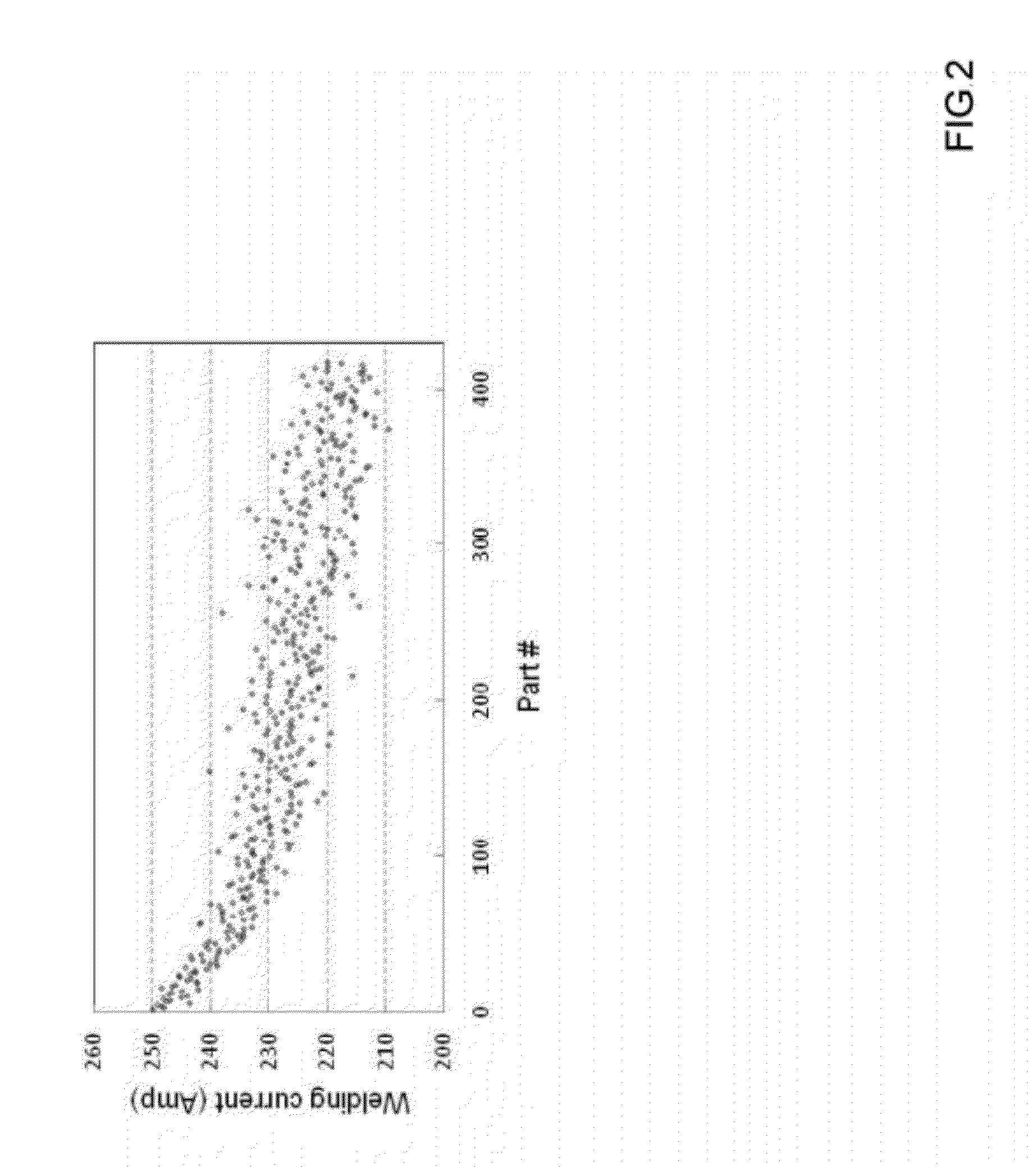
The deterioration of the contact tip in pulse GMAW applications may be caused by damage to the interface between the contact tip and the electrode wire caused by mechanical wear, high temperature of the welding arc, joule heat from the electric conductivity, and possible micro-arcing during pulse peaks.
The electrical resistance of the interface between the contact tip and the electrode wire increases as the contact tip is deteriorated.
When a standard power source control mechanism is used, the increased resistance of the contact tip / electrode wire interface results in a decrease in the energy consumption at the welding arc.
If the energy consumption falls below a certain threshold value, a smooth arc cannot be maintained, resulting in welding defects.

Method used


Image

  • Method for providing real-time monitoring of contact tip performance
  • Method for providing real-time monitoring of contact tip performance
  • Method for providing real-time monitoring of contact tip performance

Examples


Embodiment Construction

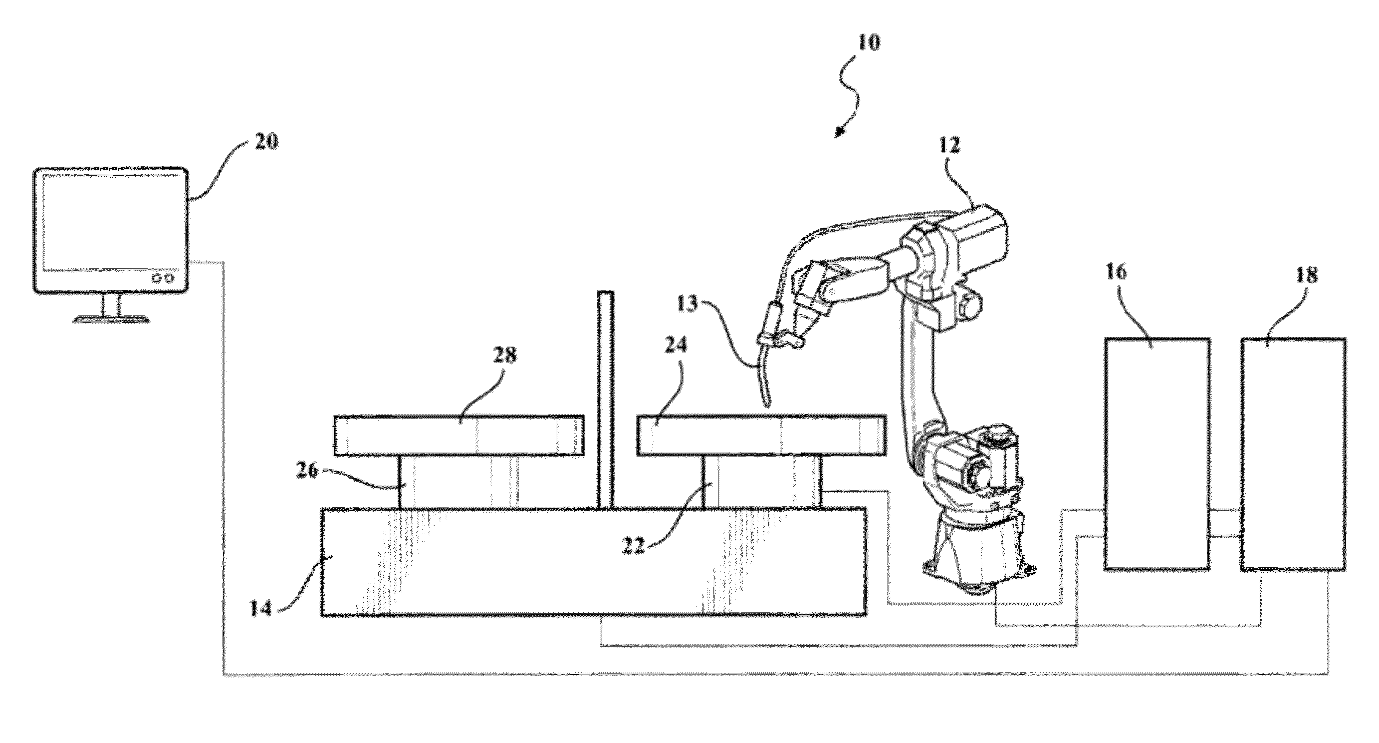
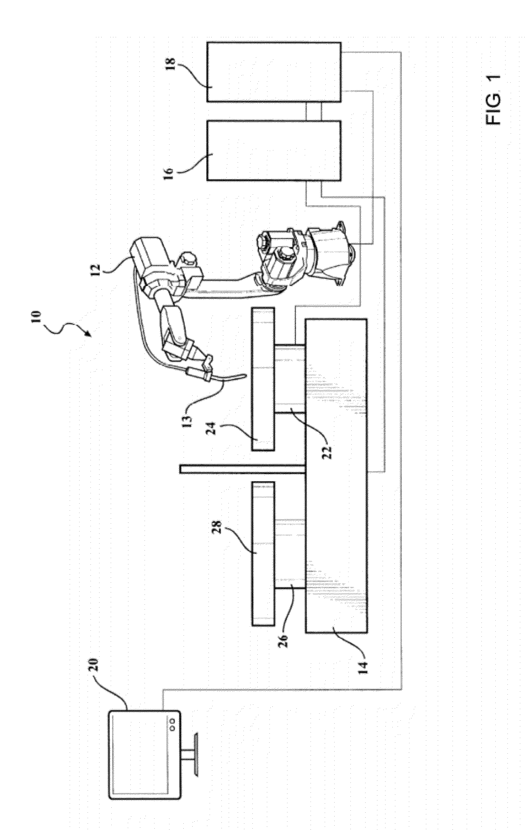
[0019]Referring now to the drawings in detail, numeral 10 in FIG. 1 generally indicates a robotic welding manufacturing cell. The welding cell 10 generally includes a welding robot 12 including a welding torch 13, a turn table 14 disposed in a working relationship relative to the robot, a power source 16 connected to the robot, a robot controller 18 connected to the power source, the robot, and the turn table, and a manufacture line display and control (MLDC) 20. The turn table 14 may have two sides including an A-side 22 that holds a workpiece such as part 24 and a B-side 26 that holds a workpiece such as part 28. While part 24 is being welded by the robot 12, part 28 may be loaded / unloaded by a handling robot or a human operator.

[0020]The welding power source 16 and the robot controller 18 may be separate or may be integrated in one welding control system unit. In either case, the power source 16 and controller 18 include logic devices that directly or indirectly provide proper we...


PUM

PropertyMeasurementUnit
Currentaaaaaaaaaa

Abstract

A method for tracking contact tip deterioration in real time in accordance with the present invention includes establishing a reference that relates welding parameters during welding production to contact tip life; monitoring welding parameters of a contact tip during use; comparing the monitored welding parameters to the reference; providing real-time feedback to an operator; and predicting contact tip failure from the comparison.

Description

CROSS REFERENCE TO RELATED APPLICATION[0001]This application claims the priority of U.S. Provisional Application No. 61 / 452,385 filed Mar. 14, 2011.TECHNICAL FIELD[0002]This invention relates to contact tips for a welding torch, and more particularly to a method of monitoring performance of a contact tip in non-constant voltage GMAW (gas metal arc welding) applications.BACKGROUND OF THE INVENTION[0003]It is known in the art relating to GMAW that the life span of a contact tip in a pulse application is significantly shorter than in a conventional application (i.e., constant voltage (CV)). The deterioration of the contact tip in pulse GMAW applications may be quantified by measuring a decrease in the average welding current, an increase in the standard deviation of the welding current, and / or an increase in the average welding voltage.[0004]The deterioration of the contact tip in pulse GMAW applications may be caused by damage to the interface between the contact tip and the electrode...

Claims


Application Information

Patent Timeline
IPC IPC(8): B23K33/00
CPCB23K9/123B23K9/095
Inventor RYAN, ROBERT D.MA, TIEJUNBELLAMY, DAVID A.
Owner ILLINOIS TOOL WORKS INC
Learn More