Switch device having self-cleaning function

a switch device and self-cleaning technology, applied in the direction of snap-action arrangements, contacts, contact mechanisms, etc., can solve problems such as sliding friction

Inactive Publication Date: 2005-01-18
ALPS ALPINE CO LTD
View PDF2 Cites 6 Cited by
  • Summary
  • Abstract
  • Description
  • Claims
  • Application Information

AI Technical Summary

Benefits of technology

The present invention has been achieved in view of such drawbacks. It is therefore an object of the present invention to provide a switch device having a self-cleaning function, which prevents contact failure from being caused.

Problems solved by technology

However, at the moment when the sliding contact point that is the tip (winding terminal end) of the elastic deformation part of the movable electrode comes in contact with the surface of the counter electrode, sliding friction is caused.

Method used


Image

  • Switch device having self-cleaning function
  • Switch device having self-cleaning function
  • Switch device having self-cleaning function

Examples


first embodiment

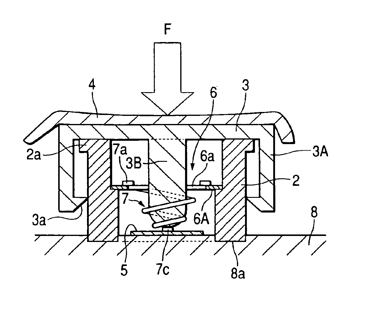
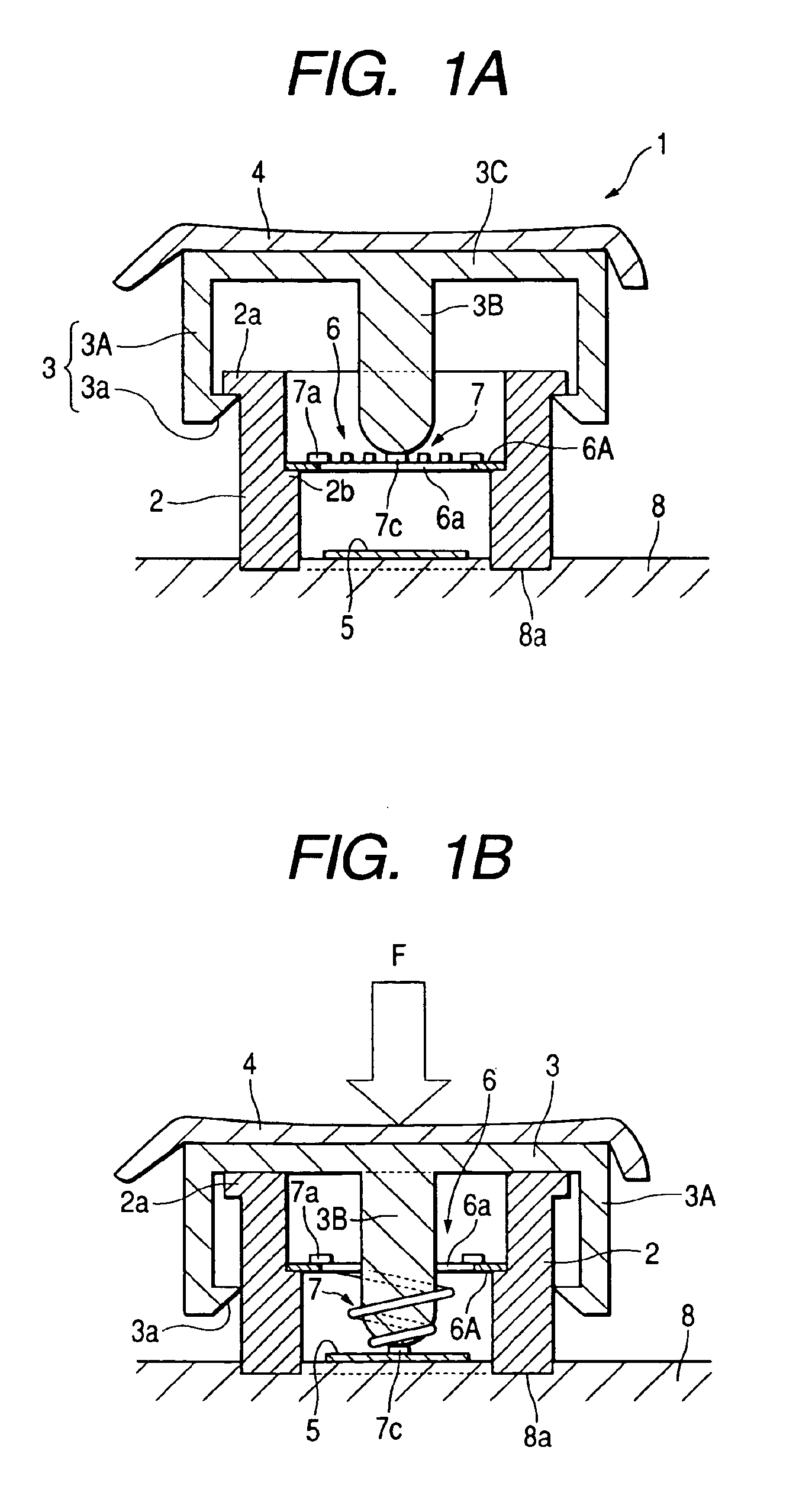
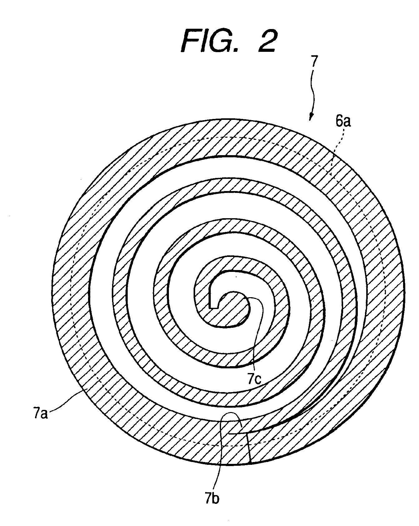
FIG. 1 is a sectional view of a switch device according to the present invention wherein FIG. 1A illustrates a state of the switch device prior to operation, FIG. 1B illustrates a state of the switch device during operation. FIG. 2 is a plan view illustrating a spiral contactor provided in a movable electrode.

As shown in FIGS. 1A and 1B, a switch device 1 according to the first embodiment of the present invention includes a key top 4 that has an actuator 3 on a case 2. The case 2 takes a cylindrical form. Also, a groove 8a, which corresponds to the shape of a lower opening end of the case 2, is formed in a board 8. The lower opening end of the case 2 is fixed to the groove 8a. An outer edge 2a that protrudes outwardly from the outer surface of the case 2 is provided around the upper opening end of the case 2. Also, a stepped part 2b is provided around the inside of the case 2 in a position to have a predetermined height dimension from the lower opening end of the case 2.

A stationary...

second embodiment

FIG. 3 is a sectional view illustrating a state of a switch device during operation, which is similar to that in FIG. 1B, according to the present invention.

The structure of a switch device 10 according to a second embodiment of the present invention is different from that of the switch device 1 according to the first embodiment of the present invention in that a stepped part 2c is formed below the stepped part 2b inside the case 2, a second movable electrode 16 whose structure is the same as the movable electrode 6 is provided in the stepped part 2c, and the stationary electrode 5 as a counter electrode is not provided on the board 8. The other structure is the same.

In other words, in the second embodiment, the movable electrode 6 and the second movable electrode 16 provided as a counter electrode are stacked parallel to each other with a predetermined distance inside the case 2. Also, the spiral contactor 7 provided in the movable electrode 6 faces the spiral contactor 17 provided...

third embodiment

FIG. 4 is a sectional view illustrating a state of the switch device during operation, which is similar to that in FIG. 3, according to the present invention.

The structure of a switch device 20 according to a third embodiment of the present invention is different from that of the switch device 10 according to the second embodiment of the present invention in that a stationary electrode 5 as a counter electrode is also provided on the surface of the board 8 inside the case 2 in addition to the second movable electrode 16 provided as a counter electrode. The other structure is the same.

In the switch device 20 shown FIG. 4, when the operation part 3B of the actuator 3 is pushed down by applying the pressing force F to the key top 4, the operation part 3B extends the spiral contactor 7 of the upper movable electrode 6 downward, the spiral contactor 7 is brought into contact with the spiral contactor 17 of the lower second movable electrode 16. At this time, the upper movable electrode 6...


PUM


Abstract

A switch device that prevents a contact failure from occurring between electrode contact points by having a self-cleaning function is provided. When a key top 4 is pushed downward, a portion between a winding start end 7b and a winding terminal end 7c of a spiral contactor 7 is extended by an operation part 3B provided in an actuator 3. At this time, the winding start end 7c slides along the surface of a stationary electrode 5. As a result, dusts or stains attached to the winding terminal end 7c and/or the stationary electrode 5, oxide films formed on the surfaces of the electrodes, etc., is self-cleaned. Therefore, it is possible to solve a contact failure problem between the movable electrode 6 and the stationary electrode 5.

Description

BACKGROUND OF THE INVENTION1. Field of the InventionThe present invention relates to a push button type switch device, and more particularly, to a switch device that prevents a contact failure from occurring at contact points.2. Description of the Related ArtFor example, Patent document 1 discloses a conventional push button type switch.In the switch disclosed in Patent document 1, when a key top is pushed down, a dowel part provided below the key top uniformly pushes a driven element down and the entire surface of a movable contact point is brought in contact with a stationary contact point, thereby functioning as a switch.Also, since the key top is returned to its original state by a resilient force of an arm when pressing against the key top is released, the key top is adapted to release the contact state between the movable contact point and the stationary contact point.[Patent Document 1]Japanese Utility Model Application Publication No. 7-31471However, the conventional switch ...

Claims


Application Information

Patent Timeline
Patent Type & Authority Patents(United States)
IPC IPC(8): H01H1/24H01H1/12H01H1/18H01H13/20H01H1/60H01H13/66
CPCH01H1/18H01H1/242H01H2235/026H01H2235/01
Inventor TSUCHIYA, JUNJIDONO, KOJI
Owner ALPS ALPINE CO LTD
Why Eureka
Try Eureka