Coordinate Transformation Device For Electrical Signal Connection

a technology of transformer and electrical signal, which is applied in the direction of measurement devices, semiconductor/solid-state device testing/measurement, instruments, etc., can solve the problems of child board high production cost, variation of terminal resistance, contact failure, etc., and achieve the effect of reducing the variation of contact resistance and preventing contact failur

Inactive Publication Date: 2008-05-22
KIMOTO GUNSEI
View PDF3 Cites 7 Cited by
  • Summary
  • Abstract
  • Description
  • Claims
  • Application Information

AI Technical Summary

Benefits of technology

[0022]Thus, the mechanical connection between the output terminal of the probe and the input terminal of the wiring group is further strengthened, thereby preventing the contact failure and reducing the variation of the contact resistances.

Problems solved by technology

This leads to the necessity of further multi-layering of the child board and further reduction of the wiring, making the child board expensive to produce.
However, in the conventional invention, after the film-laminated type probe assembly and the coordinate transformation device are laminated, the respective input / output terminals are connected by a spring force only in the z direction (pushing direction) held by each of the terminals, which has resulted in variation of the resistances of the terminals and occurrence of contact failure, or other problems.

Method used


Image

  • Coordinate Transformation Device For Electrical Signal Connection
  • Coordinate Transformation Device For Electrical Signal Connection
  • Coordinate Transformation Device For Electrical Signal Connection

Examples


Embodiment Construction

[0030]Hereinafter, a preferred embodiment of the present invention will be described with reference to the accompanying drawings. It is to be noted that the present invention is not limited to such an embodiment.

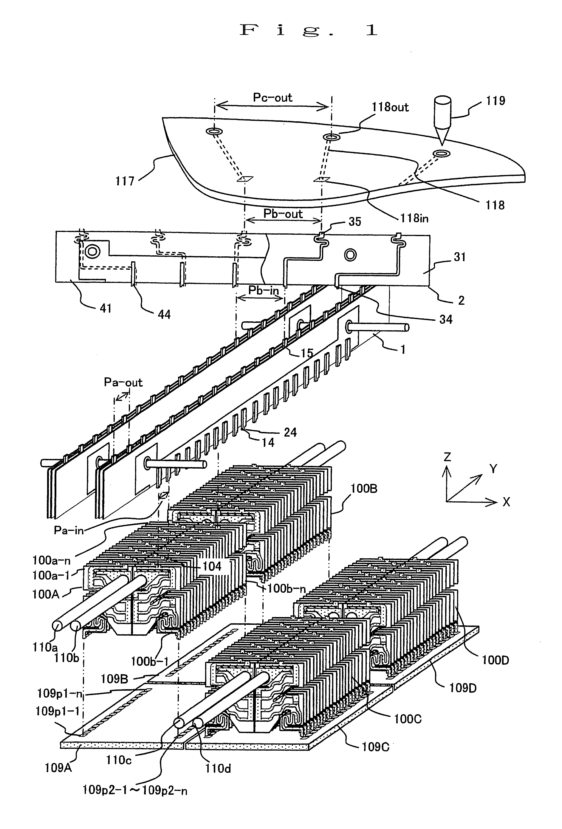
[0031]FIG. 1 shows a general assembly view of a probe structure according to an embodiment of the present invention. In FIG. 1, the configuration of film-laminated type probes and the configuration of an existing inspection apparatus printed board, which are denoted by reference numerals 100 (A to D) to 119, are the same as those in the conventional example, and the description thereof will be omitted. A difference of the present embodiment from the conventional example is in the configuration of a first wiring group 1 and a second wiring group 2 in a coordinate transformation device for electrical signal connection.

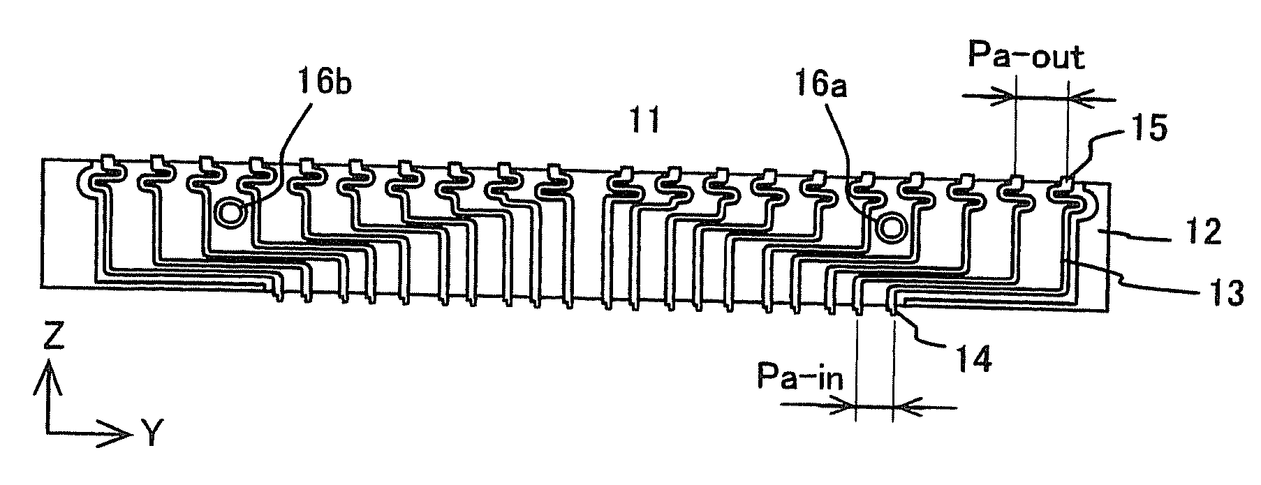
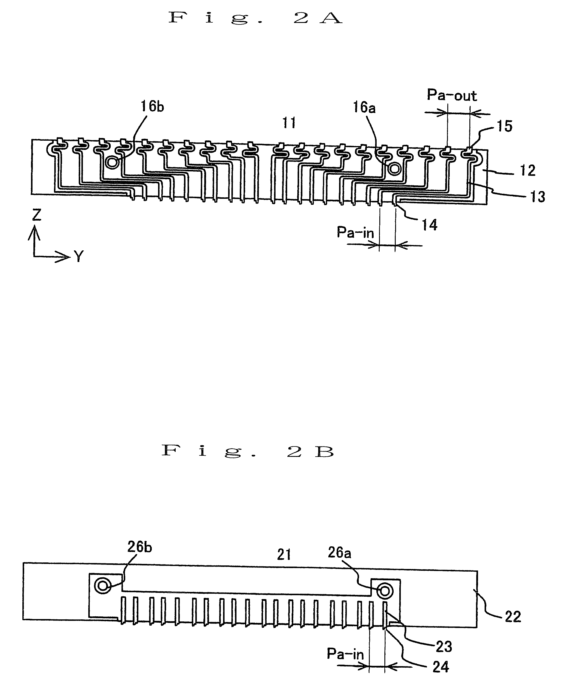
[0032]FIGS. 2A, 2B show a structure of a first (y-direction) wiring group in a coordinate transformation device for electrical signal connection according to the...


PUM


Abstract

There is disclosed a coordinate transformation device for electrical signal connection used for a probe card applicable to narrow pitch pads, which particularly simplifies wiring from the terminal onto the inspection apparatus board and prevents electrical contact failure. In the coordinate transformation device for electrical signal connection, an input terminal of a first wiring group corresponding to one of probe output terminals is provided with at least two terminals independently movable in a yz plane. When the probe output terminal and the input terminal of the first wiring group are contacted and conducted with each other, a wall surface of a first terminal of the input terminal of the first wiring group comes into contact with a side wall of the probe output terminal, and a wall surface of a second terminal thereof comes into contact with a side surface on the opposite side of the probe output terminal.

Description

BACKGROUND OF THE INVENTION[0001]1. Field of the Invention[0002]The present invention relates to a coordinate transformation device for electrical signal connection used for a probe card and the like, and more particularly to a coordinate transformation device for electrical signal connection to effectively provide wiring from contacts onto a probe card substrate.[0003]2. Description of Prior Art[0004]A probe card is used for circuit inspection of plural semiconductor chips formed on a wafer in the production process of an electronic device such as LSI. The probe card generally includes a mother board of a printed board that is provided with a common design independent of the type of semiconductor device; terminal pins that are arranged with a common design independent of the type of semiconductor device and are connected to a tester; probes arranged according to the type of the semiconductor device; and a child board of a printed board that is designed according to the type of semi...

Claims


Application Information

Patent Timeline
Patent Type & Authority Applications(United States)
IPC IPC(8): G01R31/02
CPCG01R1/07378H01L22/00
Inventor KIMOTO, GUNSEI
Owner KIMOTO GUNSEI
Why Eureka
Try Eureka