Antenna elements incorporated into the exterior structure of vehicle bodies

a technology of vehicle body and antenna elements, applied in the field of vehicle antennas, can solve the problem that the inventors do not know of any presently existing antennas

Inactive Publication Date: 2007-04-17
AEES INC
View PDF9 Cites 2 Cited by
  • Summary
  • Abstract
  • Description
  • Claims
  • Application Information

AI Technical Summary

Benefits of technology

[0010]The present invention provides an antenna that is also a structural component of the vehicle within which it is used. The antenna may, for example, form part of the support structure for the roof, for example, a roof side rail. The side rail is typically formed from a metal extrusion, such as aluminum. The side rail defines a channel therein, with a slot following the same path as the channel and providing communication between the channel and the outside. The slot permits the entry of electromagnetic radiation into the channel, which then focuses the radiation to concentrate the signal onto the associated electronics.
[0012]A barrier may be incorporated within or above the slot to resist the entrance of moisture therethrough. Such a barrier may, for example, take the form of polymeric weather stripping, which is transparent to electromagnetic radiation. Alternatively, the barrier may take the form of glass or other roof material that is transparent to electromagnetic radiation above the slot, thereby permitting the slot to form an aesthetically appealing part of the vehicle design.
[0014]Combining the antenna with the roof side rail provides the antenna without adding any additional weight to the vehicle, and provides a more streamlined vehicle.
[0019]It is a further object of the invention to provide an antenna permitting a more streamlined vehicle design.
[0020]It is another object of the invention to provide an antenna that is as high on the vehicle as possible without protruding beyond the top of the vehicle, thereby lowering the vehicle's center of gravity.
[0021]It is a further object of the invention to provide an antenna that is less easily damaged than other presently existing antennas.

Problems solved by technology

However, the present inventors are not aware of any presently existing antennas formed as part of the support structure of a vehicle's roof.

Method used


Image

  • Antenna elements incorporated into the exterior structure of vehicle bodies
  • Antenna elements incorporated into the exterior structure of vehicle bodies
  • Antenna elements incorporated into the exterior structure of vehicle bodies

Examples


Embodiment Construction

[0031]The present invention provides an antenna that is integral with a vehicle's structure.

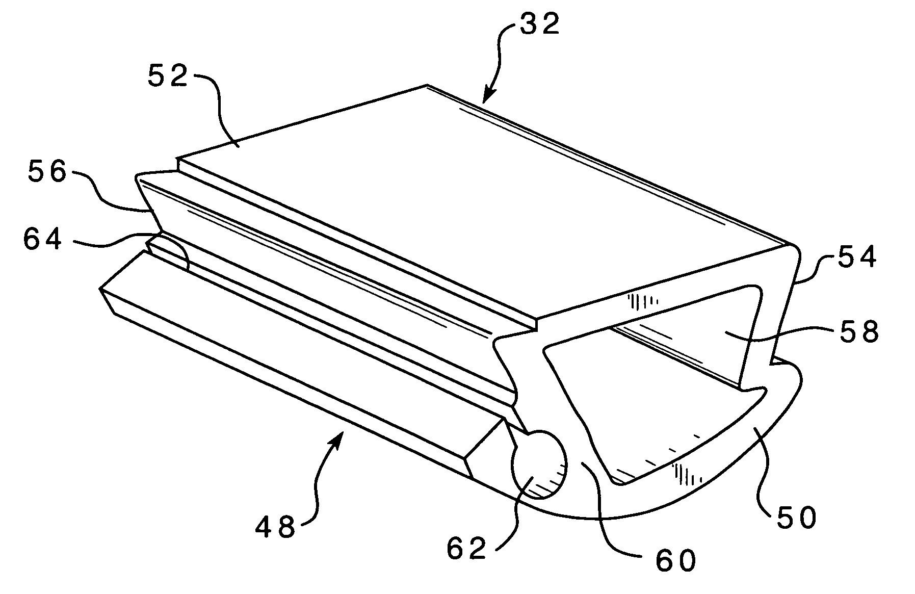
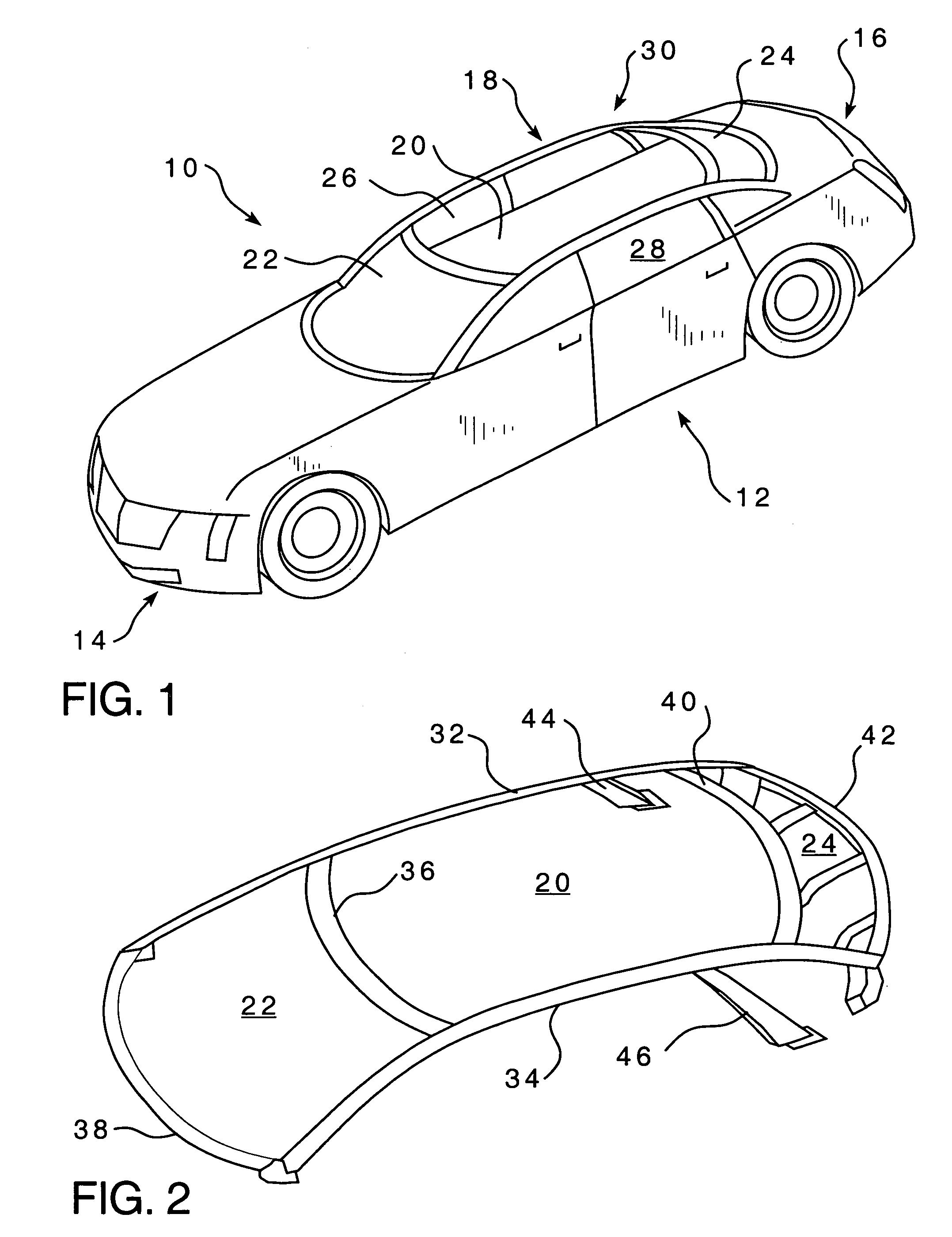
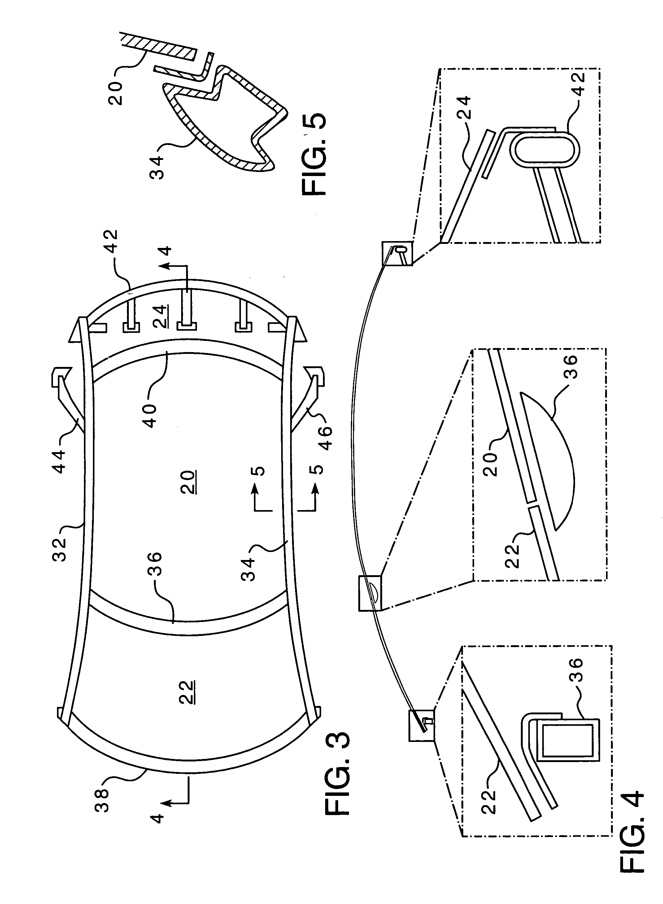
[0032]Referring to FIG. 1, a vehicle incorporating an antenna of the present invention is illustrated. A vehicle 10 includes a passenger compartment 12 between an engine compartment 14 and a trunk 16. The passenger compartment 12 includes a greenhouse 18, defined as the portion of the structure of the vehicle above the engine compartment 14 and trunk 16. The greenhouse 18 includes a roof 20, windshield 22, and rear window 24. The passenger compartment further includes side windows 26, 28. Referring to FIG. 2, the greenhouse 18 is supported by a support structure 30, which in the illustrated example includes a pair of side rails 32, 34, with upper 36 and lower 38 front cross members and upper 40 and lower 42 rear cross members extending there between. A pair of side support beams 44, 46 depend downward from the side rails, 32, 34. In the illustrated example, any of the side rails 32, 34, upper...


PUM


Abstract

An antenna is formed from one of the structural components of a vehicle with which the antenna is used. A preferred antenna is formed as a portion of a roof side rail of a vehicle.

Description

BACKGROUND OF THE INVENTION[0001]1. Field of the Invention[0002]The present invention relates to vehicle antennas. More specifically, the present invention provides a vehicle antenna formed as part of the support structure of the vehicle's roof.[0003]2. Description of the Related Art[0004]Numerous antenna structures have been proposed for use with vehicles. However, the present inventors are not aware of any presently existing antennas formed as part of the support structure of a vehicle's roof.[0005]An example of a presently available antenna is disclosed within the U.S. Pat. No. 3,289,962, issued to D. W. Young on Aug. 13, 1974. This patent discloses an antenna structured for mounting within the front edge of an airplane wing. The waveguide antenna is made from an aluminum extrusion having a T-shaped cross section and a hollow interior. One side includes a series of holes arranged in a pair of groups disposed alternately above and below the center line of the sidewall. Upper and l...

Claims


Application Information

Patent Timeline
Patent Type & Authority Patents(United States)
IPC IPC(8): H01Q1/32H01Q13/10
CPCB60R13/04H01Q1/3275H01Q13/12H01Q13/22
Inventor SABLATZKY, NEILSEKSARIA, DINESH C.
Owner AEES INC
Why Eureka
Try Eureka