Antenna
a technology of antennas and antennas, applied in the field of antennas, can solve the problems of requiring a larger area for installation, affecting the performance of antennas, so as to achieve enhanced performance, reduce size, and avoid matching and mixing losses.
- Summary
- Abstract
- Description
- Claims
- Application Information
AI Technical Summary
Benefits of technology
Problems solved by technology
Method used
Image
Examples
first embodiment
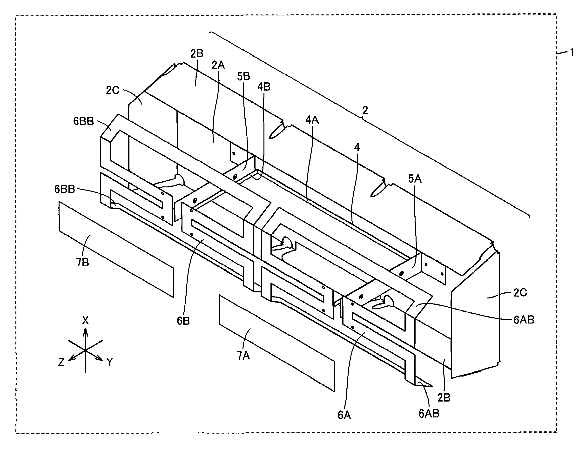
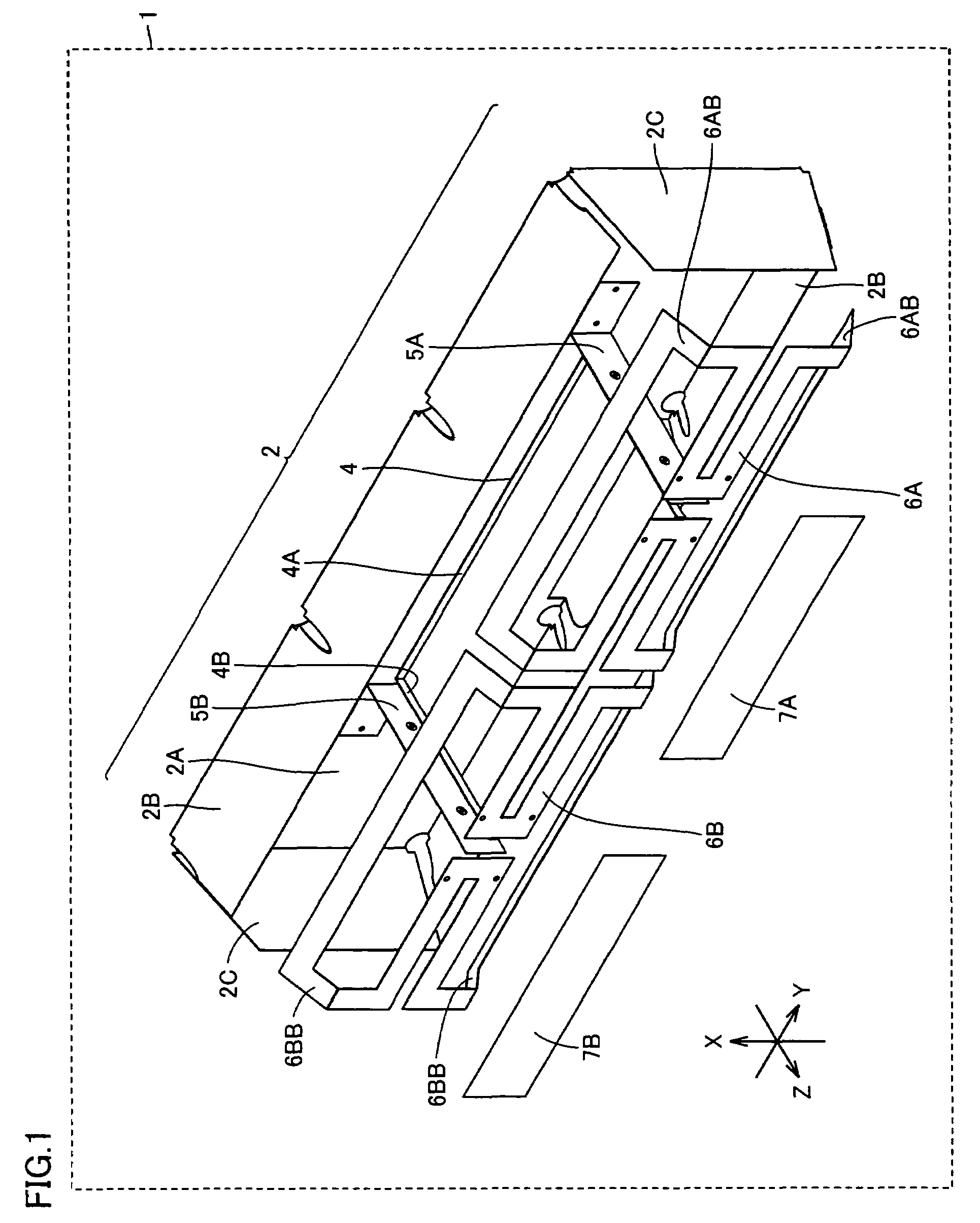
[0069]FIG. 1 is an overall view of the present antenna in a first embodiment.
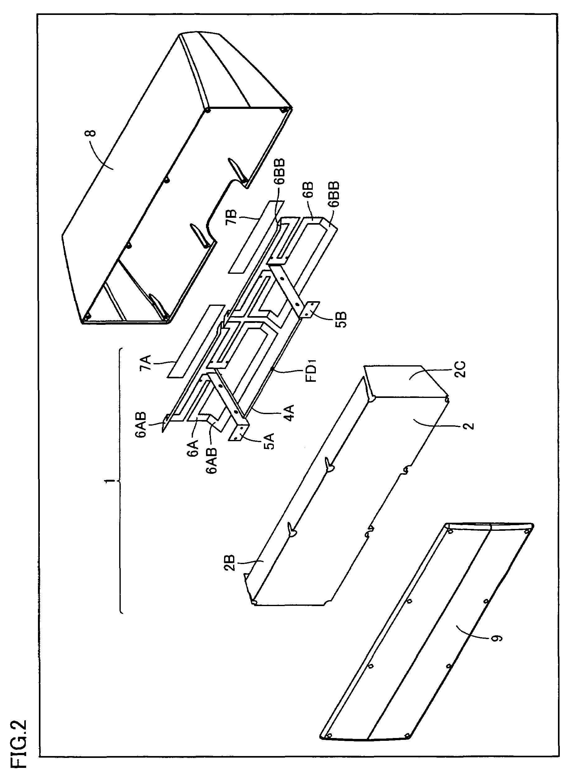
[0070]With reference to the figure, an antenna 1 includes a reflector 2, a transmission line 4, conductive plates 5A and 5B, radiators 6A and 6B, and directors 7A and 7B.
[0071]Reflector 2 includes a flat portion 2A reflecting a UHF band electric wave. Reflector 2 is formed of conductor. Note that reflector 2 includes peripheral portions 2B and 2C surrounding flat portion 2A and each forming a prescribed angle other than 180° relative to flat portion 2A. In other words, reflector 2 is provided to have a periphery bent in a direction of reflection (i.e., in the positive direction along the Z axis). Reflector 2 thus structured allows antenna 1 to be reduced in size.
[0072]Note that while FIG. 1 shows reflector 2 formed to have peripheral portions 2B and 2C both bent in the direction of reflection, reflector 2 may alternatively be formed to have one of peripheral portions 2B and 2C bent in the direction of refle...
second embodiment
[0136]FIG. 15 shows the present antenna in a second embodiment.
[0137]With reference to the figure, an antenna 1A is similar to antenna 1 except that the former includes directors 7A1 and 7B1 implemented by conductive plates.
[0138]Directors 7A and 7A1 are arranged in parallel and cooperate with flat portion 2A to sandwich radiator 6A associated therewith. Similarly, directors 7B and 7B1 and are arranged in parallel and cooperate with flat portion 2A to sandwich radiator 6B associated therewith. The plurality of directors thus provided allows the antenna to be enhanced in performance. Note that while directors 7A and 7A1 are arranged parallel to radiator 6A and directors 7B and 7B1 are arranged parallel to radiator 6B, directors 7A, 7A1, 7B, 7B1 may be arranged at an appropriate angle relative to each radiator.
[0139]FIG. 16 is the present antenna of the second embodiment in an exemplary variation.
[0140]With reference to the figure, an antenna 1B is similar to antenna 1A of FIG. 15 exc...
third embodiment
[0143]FIG. 17 is an overall view of the present antenna in a third embodiment.
[0144]With reference to the figure, an antenna 1C is similar to antenna 1 of FIG. 1 except that the former includes directors 7A3 and 7B3 instead of directors 7A and 7B.
[0145]Directors 7A3 and 7B3 each have a center and an end having different distances, respectively, from flat portion 2A. In FIG. 17, the distance between the end and flat portion 2A is smaller than that between the center and flat portion 2A. More specifically, directors 7A3 and 7B3 are both in the form of the letter U or an arc as seen in the direction of the Y axis. Directors 7A3 and 7B3 thus formed can have a smaller dimension along the X axis. Antenna 1C can thus have a reduced size.
[0146]Note that directors 7A3 and 7B3 are not limited in geometry to that shown in FIG. 17. Hereinafter an exemplary variation of the third embodiment will be described in connection with the director's geometry.
[0147]FIG. 18 shows director 7A3 of FIG. 17 i...
PUM
 Abstract
Description
Claims
Application Information
 - R&D
- Intellectual Property
- Life Sciences
- Materials
- Tech Scout
- Unparalleled Data Quality
- Higher Quality Content
- 60% Fewer Hallucinations
Browse by: Latest US Patents, China's latest patents, Technical Efficacy Thesaurus, Application Domain, Technology Topic, Popular Technical Reports.
© 2025 PatSnap. All rights reserved.Legal|Privacy policy|Modern Slavery Act Transparency Statement|Sitemap|About US| Contact US: help@patsnap.com


