
Fractal-dithering technique for image display

Inactive Publication Date: 2007-04-17
APPLE INC
View PDF3 Cites 10 Cited by
  • Summary
  • Abstract
  • Description
  • Claims
  • Application Information

AI Technical Summary

Benefits of technology

[0008]The present invention enables rapid dithering of an RGB image from a higher order to a lower order number of bits while introducing fewer undesirable artifacts than are visible in conventional dithering technology. The present invention is compact and deterministic, and enables the elimination of banding, for example as is seen in 24-bit monitors when viewing color images with greater color depth.

Problems solved by technology

For example, a computer capable of an eight-bit color map will not accurately render a 16-bit image; a computer with a 24-bit color depth cannot display an image with 48-bit color, etc.
This, however, leads to the well-known problem of Mach banding, in which the human eye exaggerates the contrast between two surfaces with different luminance, making the image look unattractive.
However, this technique causes clumps and gaps which, while minimized, are typically still visible.
Secondly, so-called error diffusion, where some statistic propagates lexicographically across the image is not local—that is, the dither algebra depends on the environment of the pixel, which can require looking at each pixel several times in addition to being computationally expensive.

Method used


Image

  • Fractal-dithering technique for image display
  • Fractal-dithering technique for image display
  • Fractal-dithering technique for image display

Examples


Embodiment Construction

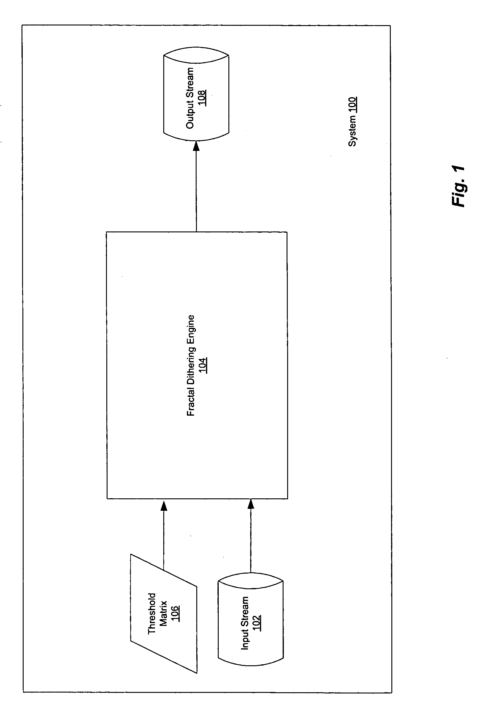
[0017]Referring now to FIG. 1, there is shown a block diagram of a system 100 in accordance with an embodiment of the present invention. System 100 includes a fractal dithering engine 104, which takes as input an input stream 102 and a threshold matrix 106, and produces an output stream 108. Images in the input stream 102 have a high order of color bits and fractal dithering engine 104 creates a stream 108 of dithered images having a lower order of color bits. The selection of an appropriate threshold matrix is detailed further below.

Using a Threshold Matrix

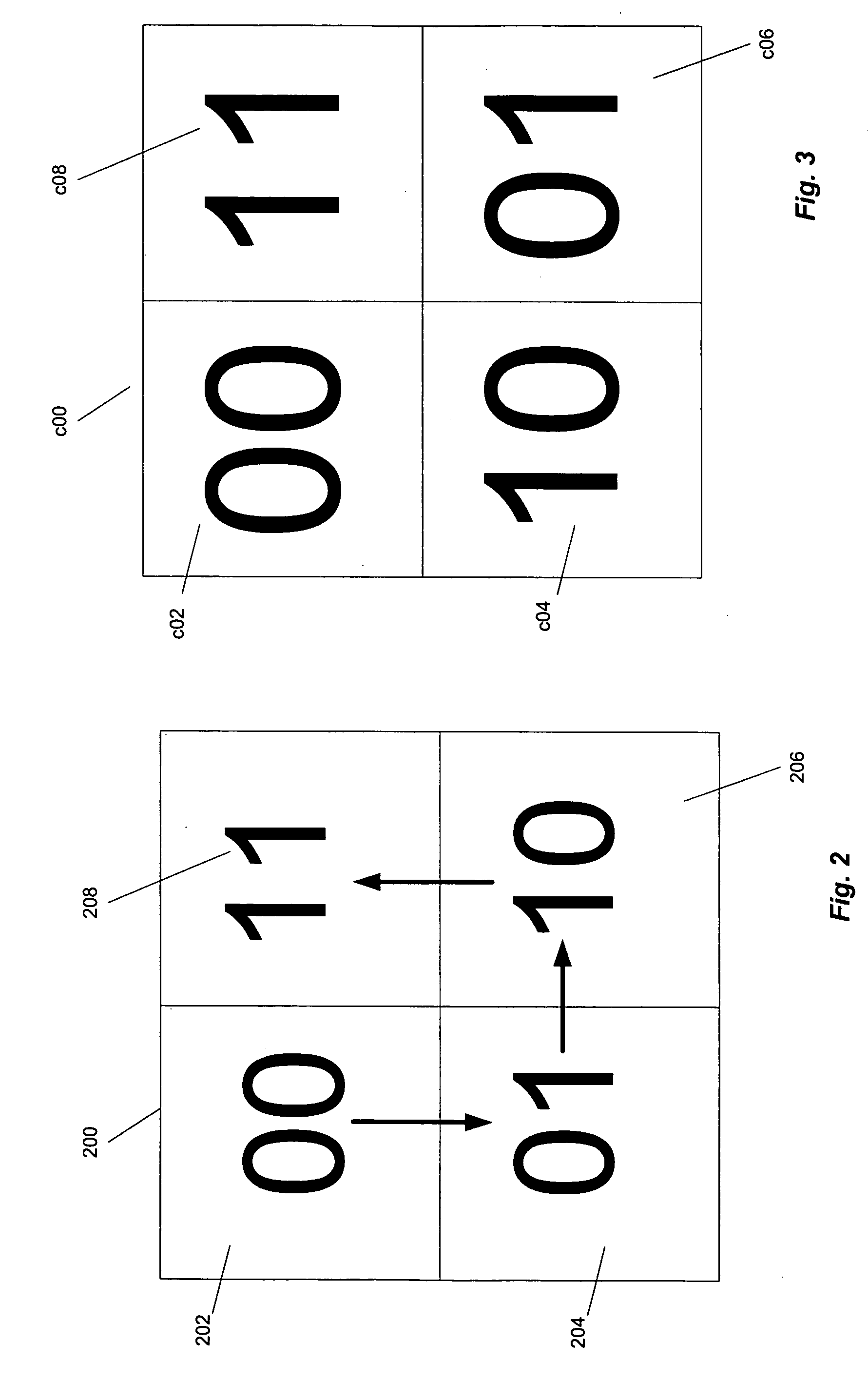
[0018]When dithering using a two-by-two threshold matrix represented by A, for a gray level g—a real number in (0, 1)—a pixel pxy at location (x, y) is turned on, e.g., to white, when

Axyg),

where the entire pixel plane is tesselated by A. In this way, (x,y,g) determines a white or black value depending on the Round inequality, so that regions of grey level g have some pixels turned on and some pixels turned off. In practice, one a...


PUM


Abstract

Rapid dithering of an RGB image from a higher order to a lower order number of bits is provided while introducing fewer undesirable artifacts than are visible in conventional dithering technology. A compact, deterministic method enables the elimination of banding, for example as is seen in 24-bit monitors when viewing color images with greater color depth. A fractal dithering engine selects a threshold matrix appropriate for an input stream, and using the threshold matrix, dithers images of the input stream to output images having a lower order number of color bits. In one embodiment, the threshold matrix is obtained by traversing 2-by-2 sub-regions of an N-by-N matrix according to a traversal pattern, and then applying a reverse binary function to the values in the original matrix to yield the threshold matrix. The threshold matrix preferably tessellates the pixel plane, subject to certain constraints.

Description

BACKGROUND OF THE INVENTION[0001]1. Field of the Invention[0002]The present invention relates generally to display of computer graphics. In particular, the present invention is directed towards a dithering technique for quickly displaying images at reduced color depth without significant quality loss.[0003]2. Description of the Related Art[0004]There is frequently a need to display an image on a display device that has insufficient color depth to display the image at its original color level. For example, a computer capable of an eight-bit color map will not accurately render a 16-bit image; a computer with a 24-bit color depth cannot display an image with 48-bit color, etc.[0005]One way of displaying such an image is to cut off the lower-order bits of each pixel in the image. This, however, leads to the well-known problem of Mach banding, in which the human eye exaggerates the contrast between two surfaces with different luminance, making the image look unattractive.[0006]Another a...

Claims


Application Information

Patent Timeline
IPC IPC(8): G09G5/02
CPCG09G3/2051G09G3/2003
Inventor CRANDALL, RICHARD EJONES, EVAN TKLIVINGTON, JASON
Owner APPLE INC
Learn More