Optical pickup device

a pickup device and optical technology, applied in the field of optical pickup devices, can solve the problems of small wave front aberration and rapid increase of wave front aberration, and achieve the effect of reducing wave front aberration

Active Publication Date: 2007-04-17
JVC KENWOOD CORP
View PDF12 Cites 17 Cited by
  • Summary
  • Abstract
  • Description
  • Claims
  • Application Information

AI Technical Summary

Benefits of technology

[0026]According to the optical pickup device of the present invention, especially with respect to the first to third laser lights incident upon the aberration correction element, a laser light flux is preferably incident upon the aberration correction element in the parallel light state rather in the divergent light state if possible. The first laser light for the first optical recording medium and the second laser light for the second optical recording medium are incident upon the aberration correction element in the parallel light state, and only the third laser light for the third optical recording medium is incident upon the aberration correction element in the divergent light state. Therefore, even when optical axes of the first and second laser lights shift slightly from the optical axis of the objective lens, deterioration of the spherical aberration is reduced. Moreover, in the incidence upon the aberration correction element, it is easier to adjust the optical axis of the parallel light than the divergent light at an assembly time. Moreover, the third laser light is incident upon the aberration correction element in the divergent light state. However, since the second laser light is incident upon the aberration correction element in the parallel light state, at this time, the divergent light of the third laser light can be incident upon the aberration correction element while the diverging degree is suppressed as compared with a conventional example. Therefore, the spherical aberration at the objective lens shift time with respect to the second and third optical recording mediums can be enhanced as compared with the conventional example.
[0028]According to the optical pickup device of the present invention, an effect similar to that of the above-described first aspect of the present invention is obtained. In addition, especially the aperture limiting portion for the third laser light is formed on the undersurface of the aberration correction element on the side of the first to third laser light sources, and the diffraction pattern portion is formed on the upper surface on the side of the objective lens. Therefore, the aberration correction element can be partially simplified, and accordingly the aberration correction element can be prepared inexpensively.

Problems solved by technology

However, in either DVD or CD, the wave front aberration is small in a case where there is not any objective lens shift.
However, when the objective lens shift is large because of a large absolute value of a magnification (incident conjugated length is short), the wave front aberration rapidly increases.

Method used


Image

  • Optical pickup device
  • Optical pickup device
  • Optical pickup device

Examples


Embodiment Construction

[0050]An embodiment of an optical pickup device according to the present invention will be described hereinafter in detail with reference to FIGS. 4 to 17.

[0051]The optical pickup device according to the present invention is characterized in that there are disposed: an objective lens designed for a first optical recording medium (extra-high density optical disc: Blu-ray Disc) having next-generation optical disc standards; and an aberration correction element for correcting a spherical aberration caused by a difference of a substrate thickness among first to third optical recording mediums at the time of using the objective lens for a case where the first to third optical recording mediums having different substrate thicknesses are selectively recorded or reproduced using first to third laser lights having different wavelengths.

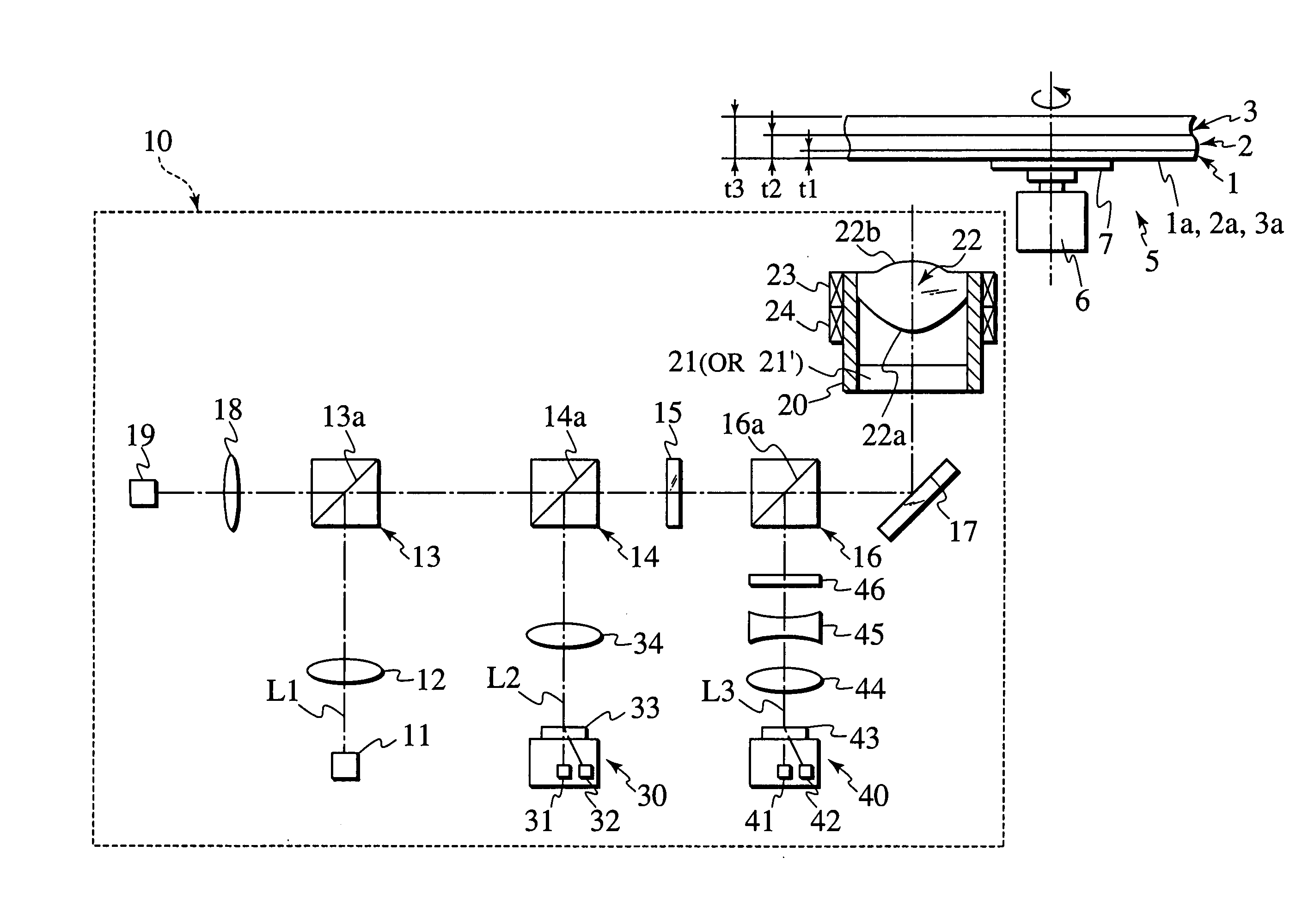
[0052]FIG. 4 is a diagram showing the whole constitution of an optical pickup device according to the present invention.

[0053]As shown in FIG. 4, an optical p...


PUM

PropertyMeasurementUnit
wavelengthaaaaaaaaaa
diameteraaaaaaaaaa
wavelengthaaaaaaaaaa

Abstract

An aberration correction element is disposed between first to third laser light sources and an objective lens, first and second laser lights emitted from the first and second laser light sources are incident upon the aberration correction element in the form of parallel lights, and a third laser light emitted from the third laser light source is incident upon the aberration correction element in the form of a divergent light.

Description

BACKGROUND OF THE INVENTION[0001]1. Field of the Invention[0002]The present invention relates to an optical pickup device comprising an objective lens having a numerical aperture (NA) of 0.75 or more, and an aberration correction element for correcting a spherical aberration generated by a difference of a substrate thickness among first to third optical recording mediums at a time when the objective lens is used, to selectively record on or reproduce from the first to third optical recording mediums different in substrate thickness using first to third laser lights having different wavelengths.[0003]2. Description of the Background Art[0004]In general, optical recording mediums such as a disc-shaped optical disc and card-shaped optical card have been frequently used, because the mediums are capable of recording information signals such as video information, sound information, and computer data in tracks spirally or concentrically formed on a transparent substrate, and capable of acc...

Claims


Application Information

Patent Timeline
Patent Type & Authority Patents(United States)
IPC IPC(8): G11B7/00G11B7/125G02B5/18G11B7/1275G11B7/135G11B7/1353G11B7/1356G11B7/1374G11B7/139G11B7/1392
CPCG11B7/1353G11B7/1356G11B7/1374G11B7/139G11B7/13922G11B7/1275G11B2007/0006
Inventor SAITOH, RYOITONAGA, MAKOTO
Owner JVC KENWOOD CORP
Why Eureka
Try Eureka