System and method for using pattern vectors for video and image coding and decoding

a pattern vector and video compression technology, applied in the field of system and method of video compression coding and decoding, can solve the problems of inefficiency of compression, related coding schemes failing to take advantage of correlations between coefficients other than those implied by fixed coefficient ordering, and theoretical arithmetic coders using unlimited precision arithmetic, etc., and achieve the effect of worsening the appearance of the reconstructed imag

Inactive Publication Date: 2007-04-17
AT&T INTPROP II L P
View PDF16 Cites 30 Cited by
  • Summary
  • Abstract
  • Description
  • Claims
  • Application Information

AI Technical Summary

Benefits of technology

[0020]The number of coefficients transformed to zero depends on the image block itself and the quantization step size. The coarser the quantization, that is, the larger the quantization step size, the more coefficients become 0 and the worse the reconstructed image looks. For typical images, the energy compaction properties of the DCT often cause the high frequency coefficients to be smaller than the low frequency coefficients. A typical image contains hundreds, or even thousands, of blocks, and a typical video segment contains tens of images every second. Effective compression depends on the fact that, on average, many of the transform coefficients for many of the blocks are zero, and can be transmitted with very few bits. The essence of the present invention is a new and better method of using a very small number of bits to indicate the zero coefficients.

Problems solved by technology

There are deficiencies in transform coding.
In addition, related coding schemes fail to take advantage of correlations between coefficients other than those implied by the fixed coefficient ordering.
Further, the use of prefix-free codes means that some compression inefficiency is inevitable.
A theoretical arithmetic coder uses unlimited precision arithmetic, and is not practical.

Method used


Image

  • System and method for using pattern vectors for video and image coding and decoding
  • System and method for using pattern vectors for video and image coding and decoding
  • System and method for using pattern vectors for video and image coding and decoding

Examples


Embodiment Construction

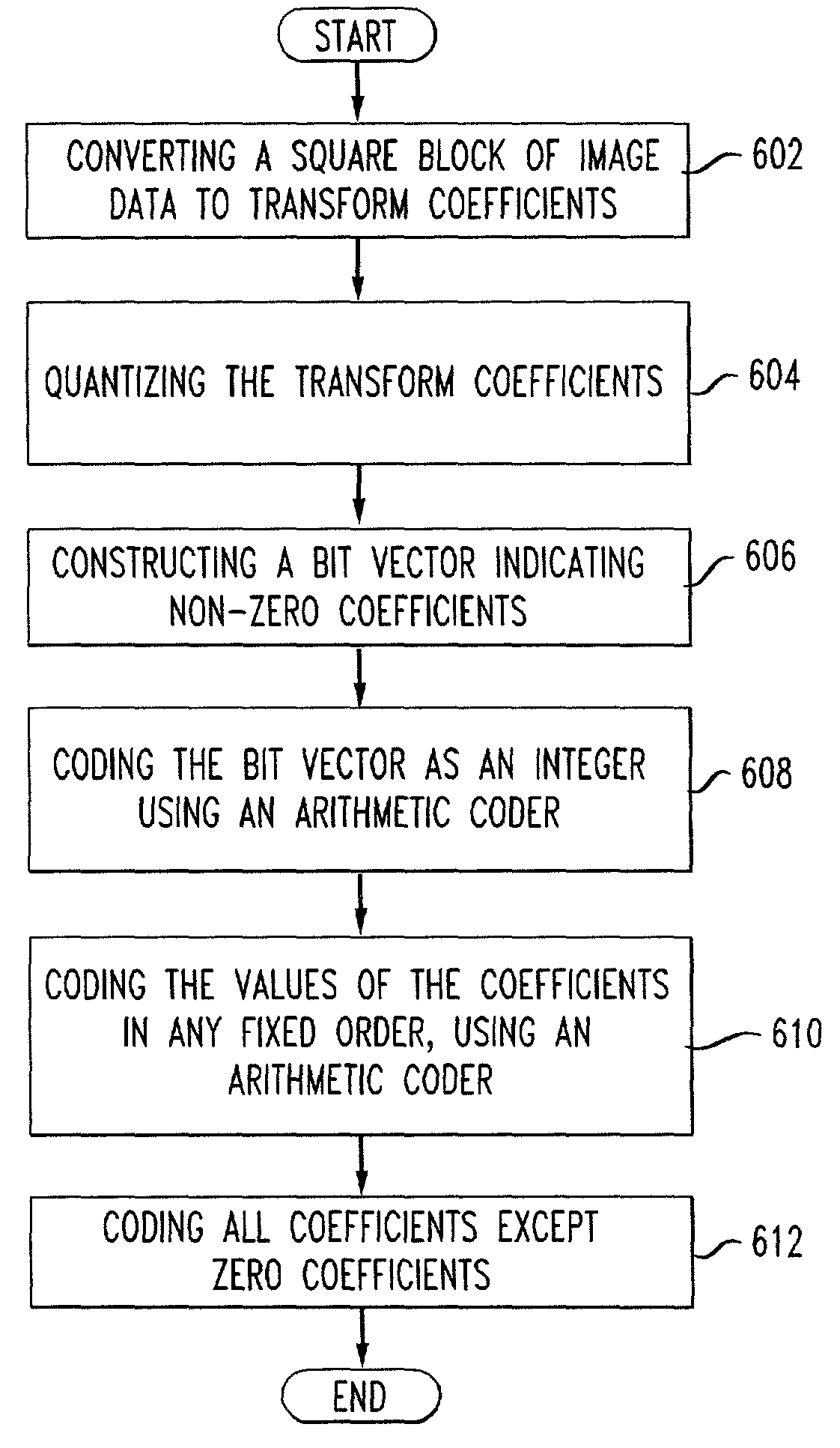
[0031]The present invention may be understood with reference to FIG. 6. FIG. 6 shows a sample method of using pattern vectors for image coding according to an aspect of the invention. The method may be performed by the hardware components known to those of skill in the art. The method comprises converting a block of image data into an array of transform coefficients (602) and quantizing the transform coefficients such that all, some or none of the coefficients become zero (604). The method further comprises constructing a bit vector indicating which coefficients are non-zero (606) and coding the bit vector as an integer using an adaptive, semi-adaptive or non-adaptive arithmetic coder (608). Those of skill in the art will be aware of such arithmetic coders. Here it is noted that although a bit vector is referenced, the core idea of the present invention does not necessarily require the use of a bit vector given that the invention's principle is that all the zero and non-zero coeffic...


PUM


Abstract

An exemplary embodiment of the invention relates to a method of using pattern vectors for image coding and decoding. The method comprises converting a block of image data into a set of transform coefficients, quantizing the transform coefficients such that a number of the coefficients become zero, constructing a single entity or bit vector indicating which coefficients are non-zero, coding the single entity or bit vector as an integer using an adaptive, semi-adaptive or non-adaptive arithmetic coder, coding the values of the coefficients in any fixed order, using an adaptive, semi-adaptive or non-adaptive arithmetic coder, or some other coder, and coding all coefficients except the zero coefficients. The system and method of decoding data relate to the corresponding hardware and process steps performed by the decoder when decoding a bitstream coded as described herein.

Description

BACKGROUND OF THE INVENTION[0001]1. Field of the Invention[0002]The present invention relates to a system and method of video compression coding and decoding and particularly to a system and method of using pattern vectors for video and image coding and decoding that eliminates two-dimensional coding of transform coefficients and the requisite zigzag scan order or alternate scan order.[0003]2. Discussion of Related Art[0004]Transform coding is the heart of several industry standards for image and video compression. Transform coding compresses image data by representing samples of an original signal with an equal number of transform coefficients. A sample of the original signal may be the signal itself, or it may be the difference between the signal and a predicted value of the signal, the prediction being done by any of a number of widely-known methods. Transform coding exploits the fact that for typical images a large amount of signal energy is concentrated in a small number of coe...

Claims


Application Information

Patent Timeline
Patent Type & Authority Patents(United States)
IPC IPC(8): G06K9/00G06T9/00H03M7/40H04N7/26H04N7/30
CPCH03M7/40H03M7/4006H04N19/176H04N19/46H04N19/196H04N19/129H04N19/00157H04N19/463H04N19/91H04N19/132H04N19/14H04N19/18G06T9/00H04N19/60H04N19/10H04N19/124H04N19/44H04N19/625H04N19/94
Inventor HOWARD, PAUL GLOR
Owner AT&T INTPROP II L P
Why Eureka
Try Eureka