Optical backplanes with integrated optical couplers and methods of making the same

a backplane and optical coupler technology, applied in the field of optical systems, can solve the problems of loss of light at the connection, loss of light, loss of light,

Active Publication Date: 2007-04-17
FUJITSU LTD
View PDF5 Cites 5 Cited by
  • Summary
  • Abstract
  • Description
  • Claims
  • Application Information

AI Technical Summary

Benefits of technology

[0005]Broadly stated, the present invention encompasses optical backplanes having focusing elements formed at or near the top surface of the optical backplane, and aligned with the ends of respective core bodies of the backplane's waveguides. The present invention eliminates the need for any optical fibers in the optical receptacle, and also eliminates the need for microlenses in either the optical receptacle or the optical ribbon connector (although microlenses may optionally be used in the optical ribbon connectors in some embodiments of the present invention). The present invention also encompasses methods for making optical backplanes with integrated optical couplers.
[0009]In this manner, the focusing element can be precisely aligned to the end of the first core body to provide good optical coupling between the end of the first core body and an external optical fiber.
[0010]Accordingly, it is an object of the present invention to increase the coupling efficiency of optical connectors and the like.
[0011]It is another object of the present invention to enable such increases in coupling efficiency without the need for expensive and time-consuming micro-alignment procedures.

Problems solved by technology

One problem with the optical ribbon connector method has been the loss of light at the connection.
Light is also lost because of misalignment between the ends of the optical fibers.
Both of these approaches, however, suffer from misalignment problems, which result in loss of light.
In addition, both of these approaches require expensive and time-consuming micro-alignment procedures to place the microlenses in their optimal locations.
Accordingly, efficient coupling of light from ribbon optical fibers to the receptacle optical fibers has not been fully achieved.

Method used


Image

  • Optical backplanes with integrated optical couplers and methods of making the same
  • Optical backplanes with integrated optical couplers and methods of making the same
  • Optical backplanes with integrated optical couplers and methods of making the same

Examples


Embodiment Construction

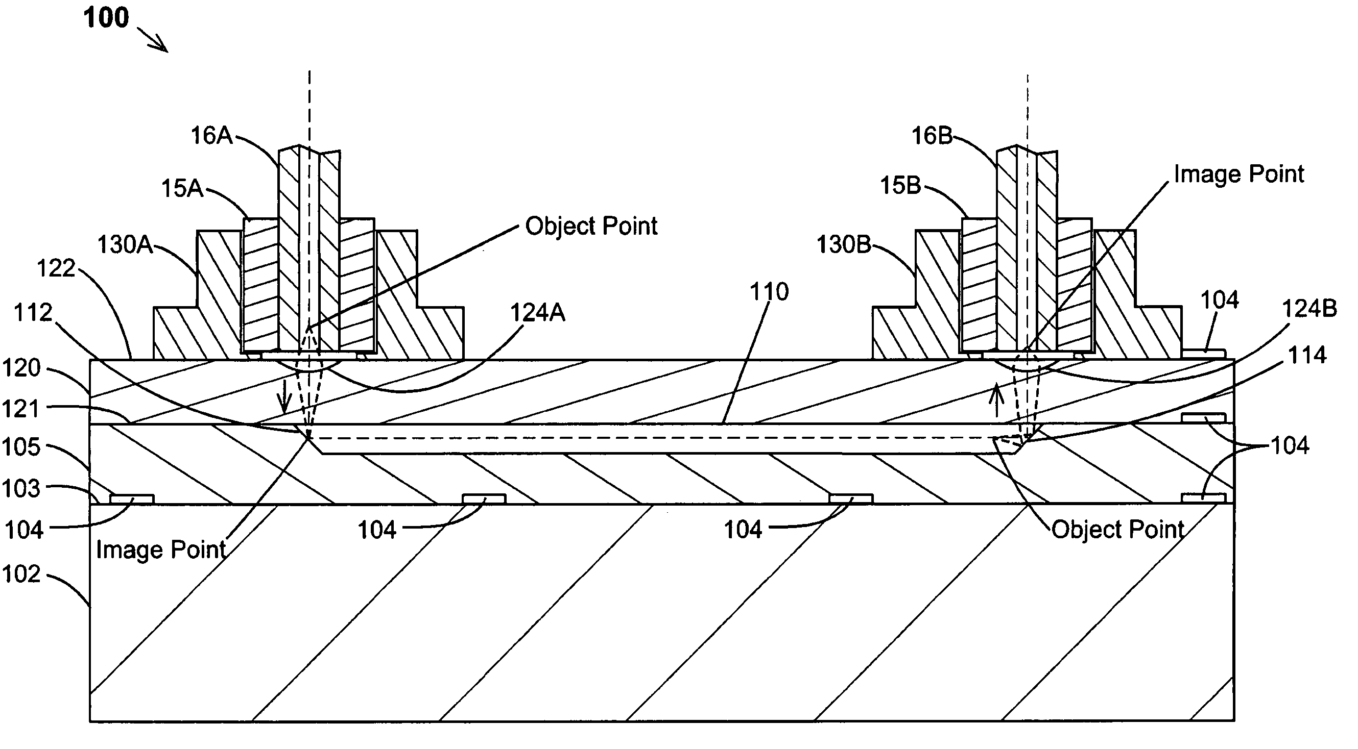
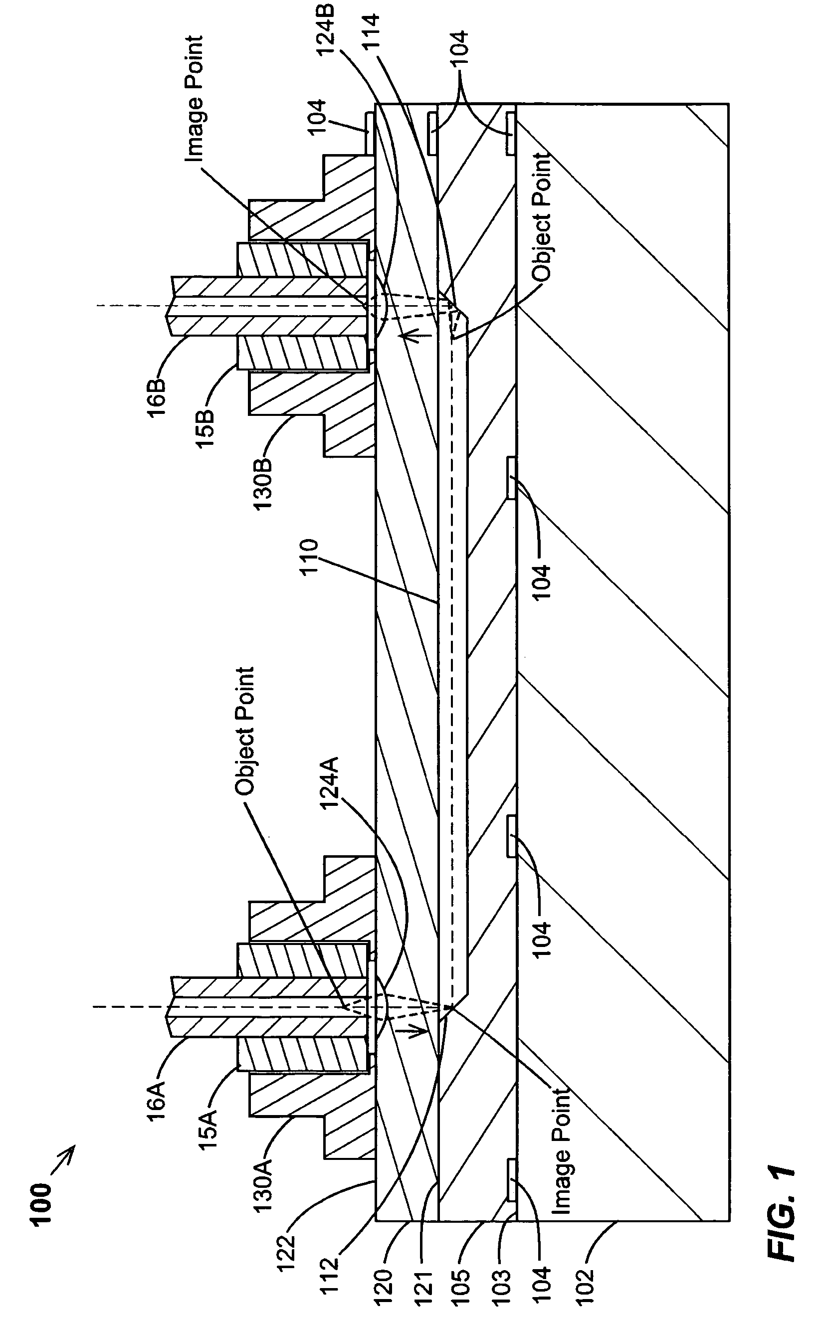
[0021]FIG. 1 shows a first embodiment 100 of an optical backplane according to the present invention, where the optical backplane may be used to provide optical interconnections among a plurality of daughterboards. Optical backplane 100 comprises a substrate 102 that has a top surface 103, a lower cladding layer 105 disposed over top surface 103 of substrate 102, and at least a first core body 110 formed over lower cladding layer 105, and a material layer 120 disposed above first cladding layer 105 and first core body 110. Material layer 120 has a top surface 122 and a bottom surface 121, and typically has a refractive index that is less than the refractive index of first core body 110, and also serves as an upper cladding layer. A waveguiding structure is thereby formed, with light being guided along core body 110, being confined by the lower refractive index of layers 105 and 120. It may be appreciated that an upper cladding layer may be disposed between first core body 110 and ma...


PUM


Abstract

Optical backplanes providing integrated optical couplers to external optical fibers are disclosed, along with methods for making the same. An exemplary optical backplane has a first cladding layer disposed over the top surface of a substrate, and at least a first core body disposed over the first cladding layer, with the first core body having a first end and a second end. A material layer is disposed above the first cladding layer and the first end of the first core body, with the material layer having a top surface and a bottom surface. A focusing element is formed at the top surface of the material layer, with the focusing element being located above the first end of the first core body.

Description

FIELD OF THE INVENTION[0001]The present invention relates to optical systems for computing and networking applications, and more particularly to optical backplanes for such systems.BACKGROUND OF THE INVENTION[0002]Today, there is a drive to replace more of the electrical interconnections in computer and networking systems with optical interconnections in order to increase computation speed and communication bandwidth. These systems typically comprise a plurality of daughterboards that are interconnected to one another by a common optical backplane. Each daughterboard has a plurality of electrical pins or tabs disposed at one of its edges, which mate with corresponding electrical receptacles on the common optical backplane. The optical connections are generally accomplished by an optical ribbon connector that runs between the daughterboard and the optical backplane. One end of the optical ribbon connector is typically anchored to the daughterboard, while the other end has an optical ...

Claims


Application Information

Patent Timeline
Patent Type & Authority Patents(United States)
IPC IPC(8): G02B6/12G02B6/124G02B6/32G02B6/34
CPCG02B6/4206G02B6/43
Inventor HUANG, LIDUYOKOUCHI, KISHIO
Owner FUJITSU LTD
Why Eureka
Try Eureka