
Glass optimization

a glass and optimization technology, applied in the field of glass optimization, can solve the problems of one or more manufacturing operations problems, waste of glass, and high manufacturing cost, and achieve the effects of increasing yield, increasing storage requirements, and reducing quality

Active Publication Date: 2007-04-17
GED INTEGRATED SOLUTIONS
View PDF6 Cites 8 Cited by
  • Summary
  • Abstract
  • Description
  • Claims
  • Application Information

AI Technical Summary

Benefits of technology

[0012]Practice of the invention significantly increases yield without the problems associated with existing methodologies discussed above such as inadequate supply, excessive inventory costs, increased storage requirements, decreased quality and reduced production throughput.

Problems solved by technology

These Low Yield Patterns or Low Yield Sheets significantly reduce the yield of entire production batches resulting in higher manufacturing costs due to wasted glass.
Waste is particularly expensive when manufacturing windows from increasingly popular specialty glasses such as Low-E or self-cleaning materials.
Unfortunately, each method presents one or more problems to manufacturing operations.
Because fillers are inserted prior to the actual manufacturing process, the number and type of filler lites rarely meet actual production demand.
Too few filler lites starve production lines while too many fillers create storage and quality problems.b) Adding different sizes of large stock sheets also increase yield.
Although this method enhances yield, it also increases inventory space and costs while decreasing throughput (more glass sizes to shuttle in and out).c) Certain cutting tables allow the lites from Low Yield Sheets to be added to manually entered or selected lites and re-optimized to increase yields.
Although these features provide excellent flexibility and increase yield, they also cause the cutting table to remain idle during the manual entry process.
This greatly reduced production throughput and efficiency.

Method used


Image

  • Glass optimization
  • Glass optimization
  • Glass optimization

Examples


Embodiment Construction

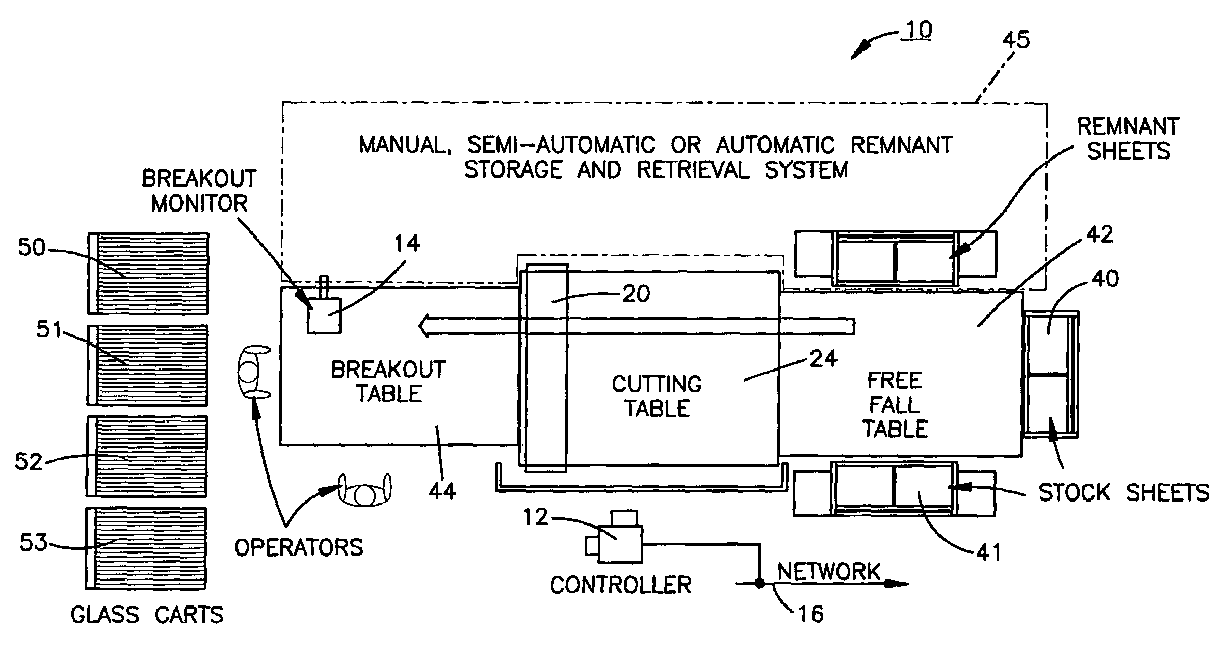
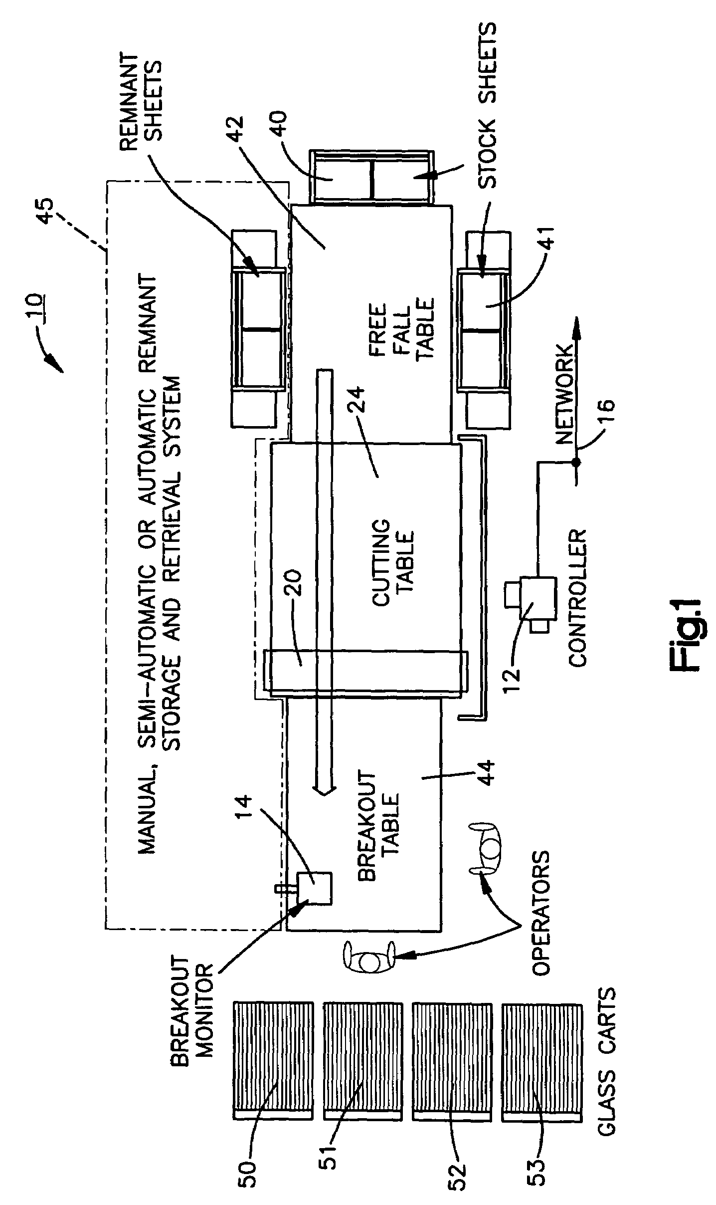
[0018]The disclosed invention provides an integrated software and apparatus solution for increasing the yield of production runs during window or door manufacture, or other manufacture requiring glass lites. An exemplar system automatically recognizes and optimizes Low Yield Sheets by adding glass lites from other production batches as well as lites entered or selected at a cutting station 10. The exemplary system also automatically creates, tracks, selects and re-cuts remnant sheets of glass if the process is unable to add sufficient lites to eliminate Low Yield Sheets from a production batch.

[0019]The FIG. 1 cutting station 10 includes a controller 12 that provides the cutting station operator an option of easily selecting filler lite sizes that can be automatically inserted into each production batch. The controller is coupled to a display or breakout monitor 14 that graphically alerts the cutting table operator(s) which cart and slot to place each lite as it is cut. The controll...


PUM

PropertyMeasurementUnit
sizeaaaaaaaaaa
timeaaaaaaaaaa
sizesaaaaaaaaaa

Abstract

A glass cutting station having a controller that lays out a pattern of lites to be cut from set of glass sheets to fulfill the lite requirements of a multiple number of cutting batches. The controller identifies one or more underutilized glass sheets in a first set of glass sheets that have free space with no lites designated to be cut in the first batch. The controller also lays out a pattern of lites to be cut to fulfill the lite requirements of an additional or second batch in the number of batches by utilizing at least some of the free space on the underutilized glass sheets of the first set of glass sheets. Additionally the controller designates other glass sheets from which to cut other lites in the additional batch. If, after this process is performed, additional free space is identified, the controller can continue to lay out the sheet with standard or filler lites that fill up the additional underutilized space of a glass sheet.

Description

CROSS REFERENCE TO RELATED APPLICATION[0001]The present application is a continuation in part application claiming priority from U.S. patent application Ser. No. 10 / 688,654, entitled GLASS OPTIMIZATION, filed Oct. 17, 2003, now abandoned which is a continuation of U.S. patent application Ser. No. 10 / 646,191, entitled GLASS OPTIMIZATION, filed Aug. 22, 2003, now abandoned which claims priority from U.S. Provisional application Ser. No. 60 / 472,060, entitled “Window or Door Glass Optimization” filed May 20, 2003.FIELD OF THE INVENTION[0002]The present invention concerns apparatus and method for cutting glass lites from large sheets of glass to achieve the highest yield.BACKGROUND ART[0003]A manufacturer of products that incorporates glass, such as a window manufacturer, receives orders for products which require different sizes of glass lites. The orders for the glass are separated and grouped into scheduled production batches. For each production batch, the glass lites are further gro...

Claims


Application Information

Patent Timeline
Patent Type & Authority Patents(United States)
IPC IPC(8): G06F19/00C03B9/40C03B9/41C03B17/06G05B19/04
CPCG05B19/4097G05B19/418G05B2219/35162G05B2219/35188G05B2219/45234Y02P90/02Y02P80/40
Inventor CLAYTON, BYRON C.MCGLINCHY, TIMOTHY B.PERRY, JR., WILLIAM V.DORSCH, PAUL VICTOR
Owner GED INTEGRATED SOLUTIONS
Learn More