Diagnostic method for predicting maintenance requirements in rotating equipment

a technology of rotating equipment and diagnostic method, which is applied in the direction of electric unknown time interval measurement, vibration measurement in solids, program control, etc., can solve the problems of spindle failure, rate of wear, and inability to predict the maintenance requirements of rotating equipmen

Active Publication Date: 2007-04-17
DOFASCO INC
View PDF13 Cites 34 Cited by
  • Summary
  • Abstract
  • Description
  • Claims
  • Application Information

AI Technical Summary

Problems solved by technology

This, however, can prove inaccurate, as the wear on the spindles is dependent on loads and utilization, which, in a plant environment, is continually changing.
Therefore, spindles may fail before their scheduled replacement time due to increased loads or other problems that increase the rate of wear.
In addition, spindles may be replaced prematurely, simply because the scheduled replacement date has arrived.
This results in a decrease in productivity, as well as increased maintenance costs.
While effective, this system is costly and, therefore, users often find it too expensive to justify its implementation in large plant environments.
Also, within plant environments, there is such significant damage to these systems that continuous replacement make them impractical.

Method used


Image

  • Diagnostic method for predicting maintenance requirements in rotating equipment
  • Diagnostic method for predicting maintenance requirements in rotating equipment
  • Diagnostic method for predicting maintenance requirements in rotating equipment

Examples


Embodiment Construction

[0016]The invention will be described with reference to a specific application for monitoring the condition of drive spindles used in a hot strip mill used in the production of flat rolled steel. It will be understood that the invention may find applications in other environments which include rotating equipment that operates in loaded and unloaded conditions. In the case of this invention, Rotating Equipment can be defined as any equipment consisting of a power source, a transmission medium and a power sink.

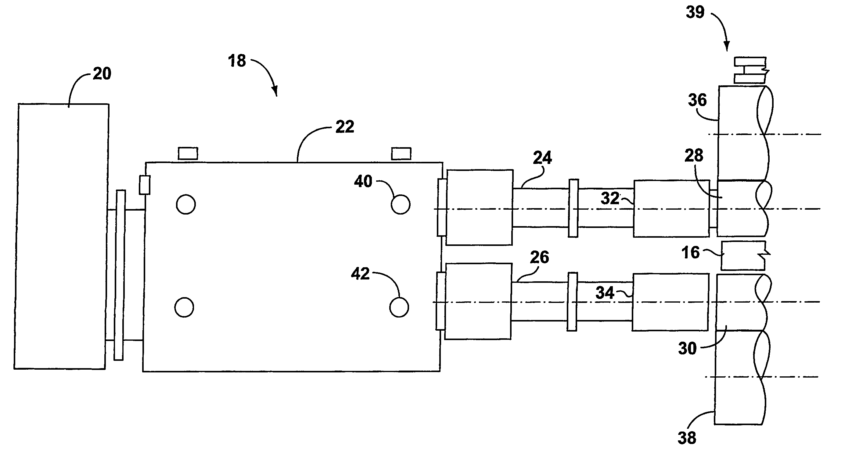
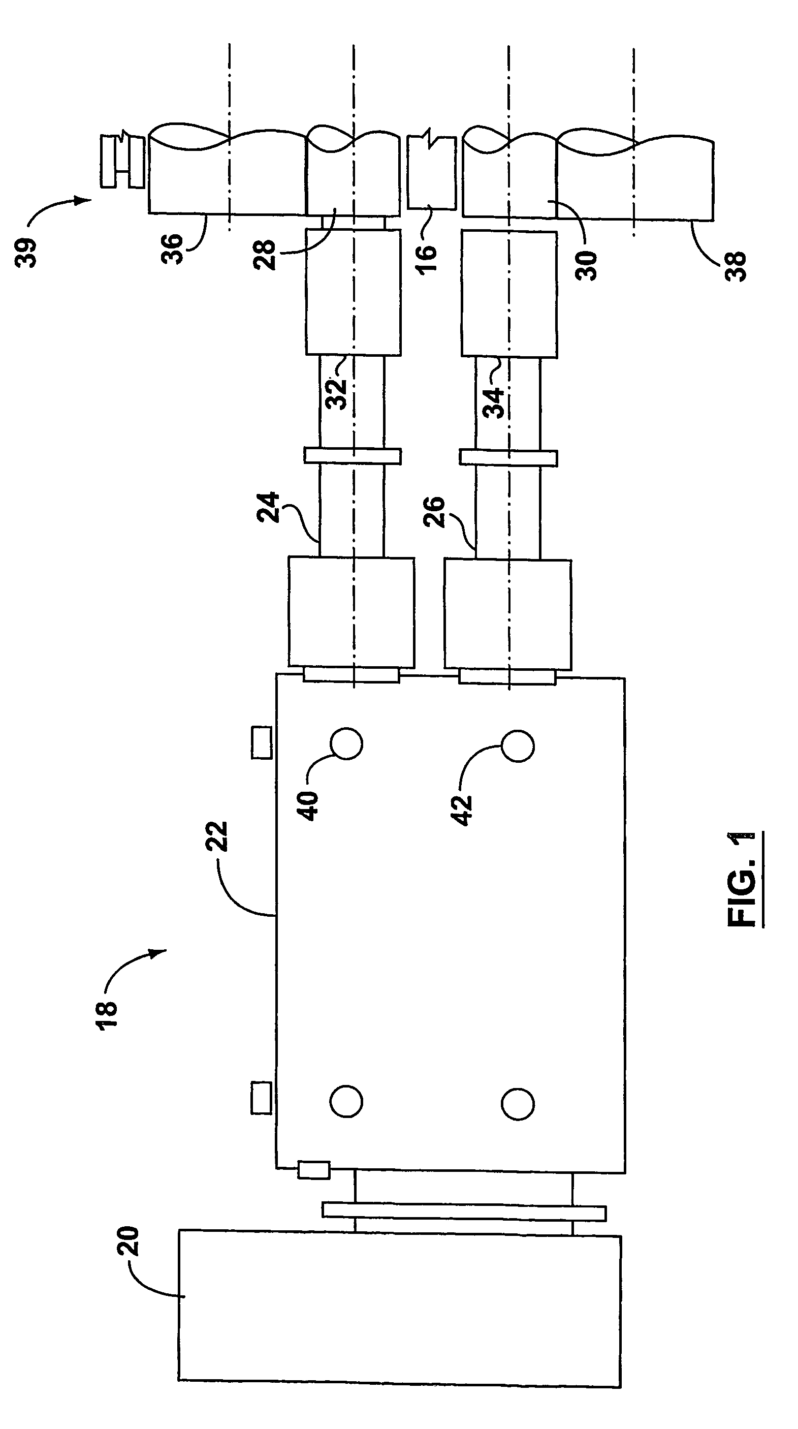
[0017]In a finishing mill rolling process of a hot strip mill shown schematically in FIG. 1, hot strip steel is threaded through and is reduced in thickness by several mill stands, which are individually driven. The rotating speed of mill drives increases as strip progresses through the process. The steel 16 is compressed and rolled out as it travels through each mill stand to achieve the desired gauge, shape, and length.

[0018]A typical drive train 18 is described with reference...


PUM

PropertyMeasurementUnit
frequencyaaaaaaaaaa
frequencyaaaaaaaaaa
timeaaaaaaaaaa

Abstract

This invention is a method to determine the condition of rotating equipment, namely drive spindles, to enable the timely maintenance or replacement of same. The method uses an electrical signal from a vibration sensor mounted on part of the drive train to measure the level of vibration energy when the equipment is rotating under loaded and unloaded conditions. The relative vibration under the loaded and unloaded conditions is used as an indicator of equipment condition. Typically there is more vibration under load when the equipment is in good condition. When the level of vibration under the no-load condition matches or exceeds that seen under load, the equipment needs to be serviced or replaced.

Description

FIELD OF THE INVENTION[0001]This invention relates to monitoring of wear conditions on rotating shaft equipment in a plant environment, such as drive spindles for work rolls to reduce the thickness of cast metal slabs. It will however be understood that the invention will likewise find application for monitoring other types of rotating equipment, such as fans, motors, roll out tables, pumps, etc.BACKGROUND OF THE INVENTION[0002]It is common practice to monitor the spindles on rolling mills to avoid catastrophic spindle failures and resultant damage. Commonly, the spindles are monitored and replaced according to a time-based system. This, however, can prove inaccurate, as the wear on the spindles is dependent on loads and utilization, which, in a plant environment, is continually changing. Therefore, spindles may fail before their scheduled replacement time due to increased loads or other problems that increase the rate of wear. In addition, spindles may be replaced prematurely, simp...

Claims


Application Information

Patent Timeline
Patent Type & Authority Patents(United States)
IPC IPC(8): G06F15/00B21B28/00B21B38/00G05B23/02
CPCB21B38/00B21B38/008G05B19/4065G05B23/0283B21B28/00G05B2219/37434G05B2219/37435
Inventor LINDSAY, WILLIAMHUNT, KEVIN GSTULEN, JAMES F
Owner DOFASCO INC
Why Eureka
Try Eureka