Method of manufacturing an endodontic instrument

a manufacturing method and endodontic technology, applied in the field of endodontic instruments, can solve the problems of introducing machining stresses into the material, affecting the quality of endodontic instruments, etc., to achieve the effect of increasing surface hardness, reducing machining stress, and reducing machining stress

Inactive Publication Date: 2007-04-24
ORMCO CORP
View PDF27 Cites 32 Cited by
  • Summary
  • Abstract
  • Description
  • Claims
  • Application Information

AI Technical Summary

Benefits of technology

[0011]The present invention further provides a method for manufacturing endodontic instruments having either helical or non-helical flutes, having hard surfaces with a non-directional surface finish and resilient cutting edges, and having both flexibility and resistance to torsional breakage. To this end, flutes are formed in an instrument blank by either EDM or ECM. EDM refers to machining methods including electrical discharge machining, wire electrical discharge machining and electrical discharge grinding. ECM refers to electrochemical machining. Using either an EDM or ECM process, material is removed from the instrument blank in the desired flute pattern with at least about 25% of the diameter of the instrument blank being removed at a point of maximum metal removal. The EDM or ECM process disintegrates the surface material, and as it cools, at least a portion of the removed material re-deposits onto the surface being machined, i.e. onto the flutes being formed, to form a recast layer. The recast layer on the instrument has a surface hardness that is at least about 15% greater, such as about 15–25% greater, than the hardness of the material forming the instrument blank. Thus, surface hardness is increased along the flutes, which provides a significantly harder and more resilient cutting edge for the endodontic instrument. Additionally, the EDM or ECM process produces a non-directional surface finish, thereby avoiding inducement of early material failure propagated by the directional surface finish that results from conventional grinding techniques.
[0012]In one exemplary method of the present invention, by rotating the instrument blank about its center longitudinal axis, while advancing the instrument blank past an electrode, helical flutes may be formed. In an alternative exemplary method of the present invention, by holding the instrument blank stationary while advancing an electrode past the instrument blank, non-helical flutes in axial alignment may be formed. There is thus provided a method for efficiently producing precision endodontic instruments with minimal distortion, non-directional surface finish, and with hardened cutting edges along the working length of the instrument in both helical and non-helical flute designs.
[0013]The present invention further provides a method in which the instrument blank is formed by EDM or ECM, followed by twisting the blank at low temperature to form helical flutes, thereby providing a low temperature twisting method with the benefits of surface finish and hardness achieved by EDM and ECM.

Problems solved by technology

The flute grinding process, however, produces a directional surface finish along the cutting axis which propagates early material failure, introduces machining stresses into the material, and cuts across the grain structure of the instrument blank.
In addition, these direct grinding methods are time consuming and expensive.
They also limit the variety of cross-sectional shapes that may be formed in the final product.
Carbon and stainless steel instruments are generally stiff, which may lead to errors during root canal therapy.
The use of superelastic material, however, causes some significant manufacturing concerns due to the tendency of the material to return to its original shape after the release of an applied force.
Moreover, if superelastic blanks are over-stressed, such as by being twisted too much during the fluting procedure, the material is subject to failure.
These direct grinding methods are time consuming and expensive.
They also limit the variety of cross sectional shapes that may be formed in the final product.
The heated liquids, however, are generally corrosive to the tooling.

Method used


Image

  • Method of manufacturing an endodontic instrument
  • Method of manufacturing an endodontic instrument
  • Method of manufacturing an endodontic instrument

Examples


Embodiment Construction

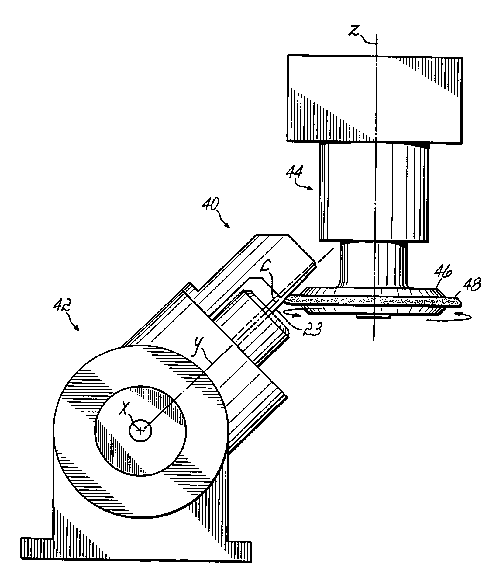
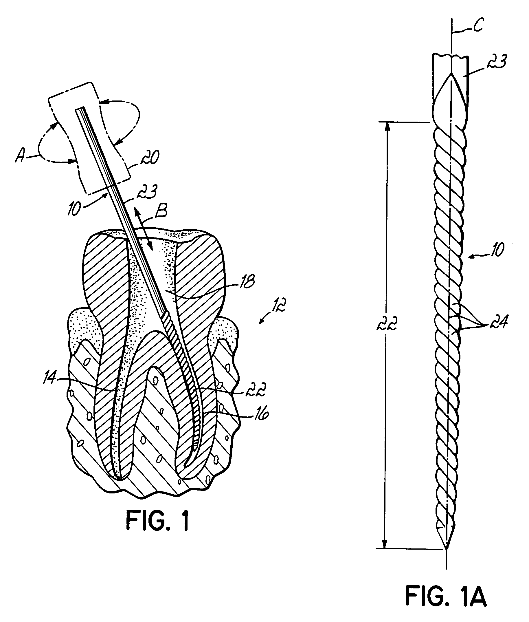
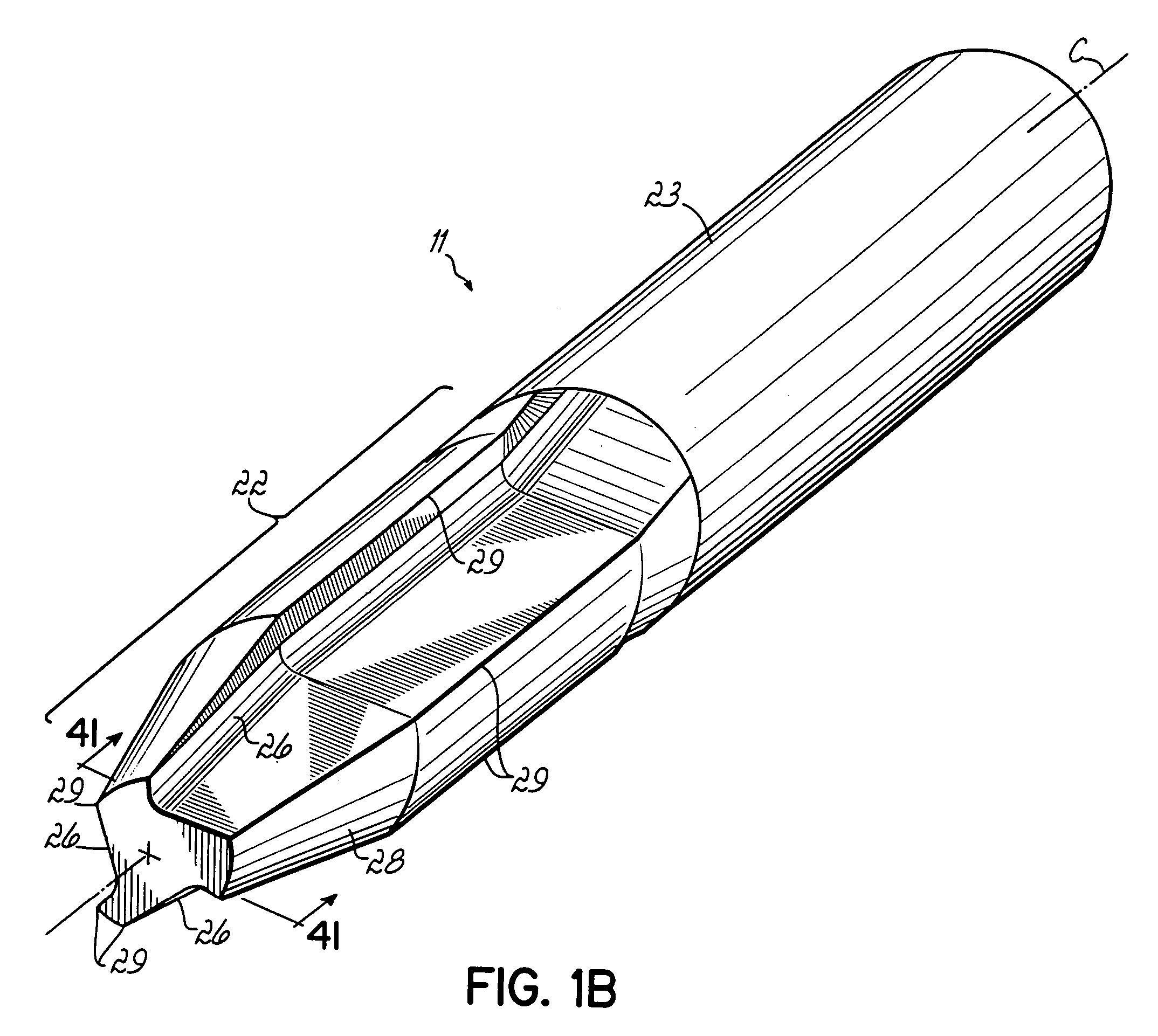
[0021]Throughout the figures, like reference numerals are used to refer to like parts. Referring first to FIG. 1, an endodontic instrument 10 constructed in accordance with an embodiment of the present invention is shown being used during a root canal procedure on a tooth 12. Tooth 12 includes root canals 14, 16 and an upper interior portion 18 which has been initially opened using another instrument, such as a drill (not shown). Instrument 10 includes a handle 20 for manual gripping by, for example, an endodontist and a working length 22 having flutes, as will be discussed in more detail below. Although these instruments are typically manipulated manually, the invention may be adapted to power-operated instruments as well. In a conventional manner, instrument 10 may be rotated in the direction of arrows “A” and reciprocated in the direction of arrow “B” by the endodontist to clean out and enlarge root canal 16. The working length 22 of the instrument 10 may include helical flutes 2...


PUM

PropertyMeasurementUnit
temperatureaaaaaaaaaa

Abstract

Method for manufacturing endodontic instruments having either helical or non-helical flutes with hard surfaces and resilient cutting edges by either an EDM or ECM process, wherein material is removed from the instrument blank in the desired flute pattern. The EDM or ECM process disintegrates the surface material, and as it cools, at least a portion of the removed material re-deposits onto the surface being machined to form a recast layer having a surface hardness that is at least about 15% greater than the hardness of the material forming the instrument blank.

Description

CROSS REFERENCE TO RELATED APPLICATION[0001]This application is a divisional of U.S. patent application Ser. No. 10 / 125,673 filed Apr. 18, 2002, now U.S. Pat. No. 6,783,438 and entitled METHOD OF MANUFACTURING AN ENDODONTIC INSTRUMENT, the disclosure of which is incorporated herein by reference in its entirety as if completely set forth herein below.FIELD OF THE INVENTION[0002]The present invention generally relates to endodontic instruments, such as files and reamers, and more specifically, to those instruments especially useful in root canal procedures.BACKGROUND OF THE INVENTION[0003]Endodontists use various types of instruments for cleaning and enlarging the root canals of the teeth. In a typical root canal procedure, an endodontist first makes an opening in the surface of the tooth to provide access to the interior. The endodontist then utilizes small instruments, such as hand-held files and reamers, to clean and enlarge the narrow, tapered root canals. In a conventional proced...

Claims


Application Information

Patent Timeline
Patent Type & Authority Patents(United States)
IPC IPC(8): A61C5/10B21F43/00A61C5/02A61C5/77B21F7/00B21F99/00B21K5/04B23H9/00B23P15/00C21D8/06C22F1/00
CPCA61C5/023B21F7/00B21F45/008B21F99/00B21K5/04B23P15/00C22F1/006B23H9/00Y10T29/49567C21D8/065C21D2201/01Y10T29/49568A61C5/42B23H7/12
Inventor ALOISE, CARLOS A.GARMAN, GARY T.
Owner ORMCO CORP
Why Eureka
Try Eureka