Impeller for radial-flow heat dissipating fan

a technology of radial flow and impeller, which is applied in the direction of liquid fuel engines, vessel construction, marine propulsion, etc., can solve the problems of limiting the amount of incoming axial airflow, affecting the rotational efficiency of the impeller, and blowing noise, so as to increase the amount of air inlet and increase the outlet wind pressure

Active Publication Date: 2007-04-24
CHINOOK SCIENCES +1
View PDF6 Cites 20 Cited by
  • Summary
  • Abstract
  • Description
  • Claims
  • Application Information

AI Technical Summary

Benefits of technology

[0009]In accordance with an aspect of the present invention, an impeller for a radial-flow heat dissipating fan comprises a hub, a plurality of blades surrounding the hub, and means for connecting the blades to the circumference of the hub, allowing joint rotation of the hub and the blades. The impeller includes an air inlet side and a bottom side. Distribution of the blades at the air inlet side of the impeller is sparser than that at the bottom side of the impeller, thereby increasing an air inlet amount.
[0011]Some of the blades have an axial level higher than the hub, forming a buffering space between the blades and a top face of the hub for increasing the air inlet area and for assisting in change of axial incoming airflow into centrifugal airflow.

Problems solved by technology

Although the above radial-flow heat dissipating fans are widely used in computers, there are still several problems.
Thus, the incoming air can only pass through the inlet 21 via the gap between the blades 33, resulting in limitation to the amount of the incoming axial airflow.
Secondly, if the other edge 33a of each blade 33 has a relatively long radial length, the incoming axial airflow entering the casing 1 via the inlet 21 is directly guided by the rotation of the edge 33a and thus turns into centrifugal airflow, leading to blowing noise and adversely affect to the rotational efficiency of the impeller.

Method used


Image

  • Impeller for radial-flow heat dissipating fan
  • Impeller for radial-flow heat dissipating fan
  • Impeller for radial-flow heat dissipating fan

Examples


first embodiment

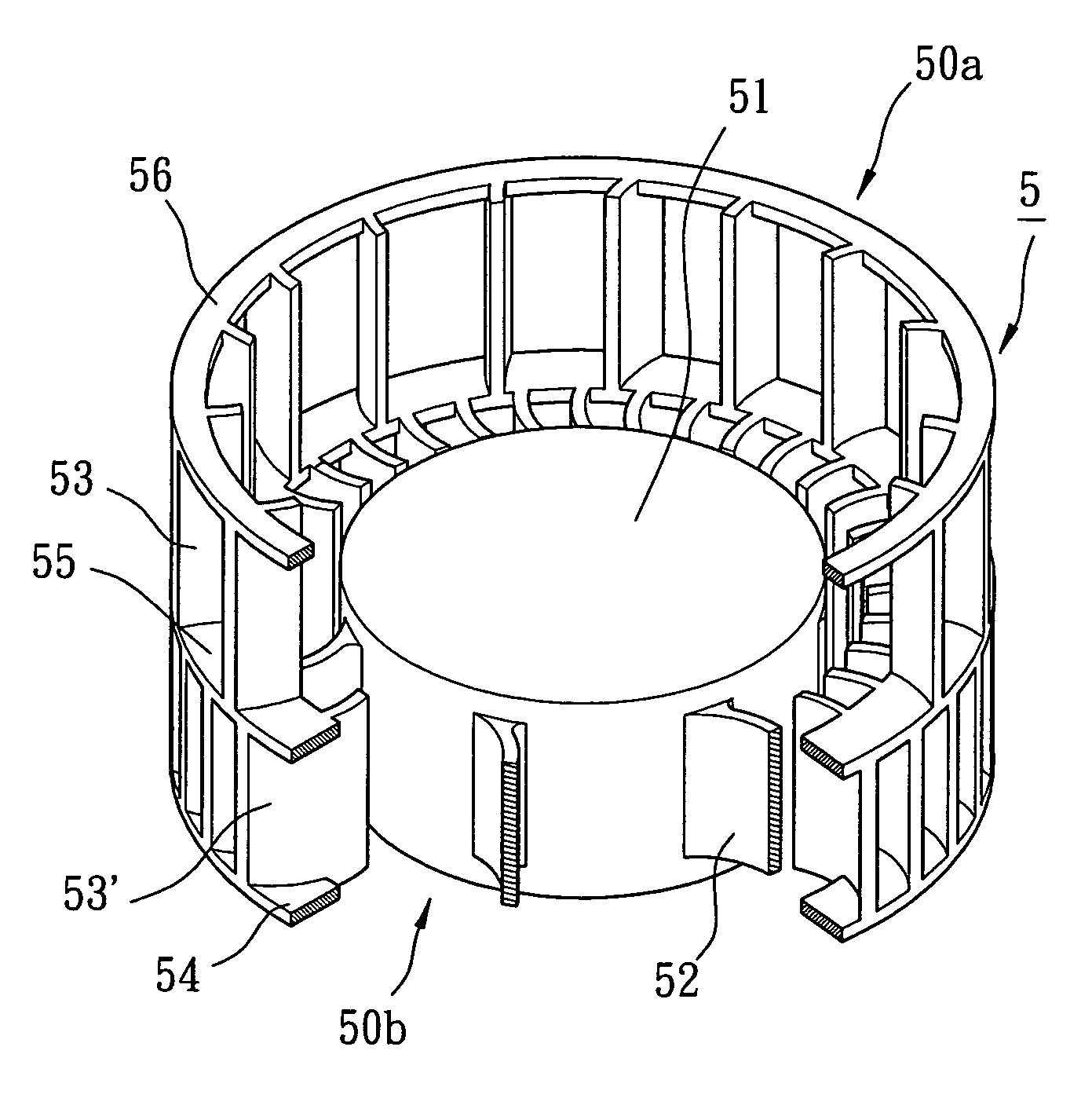
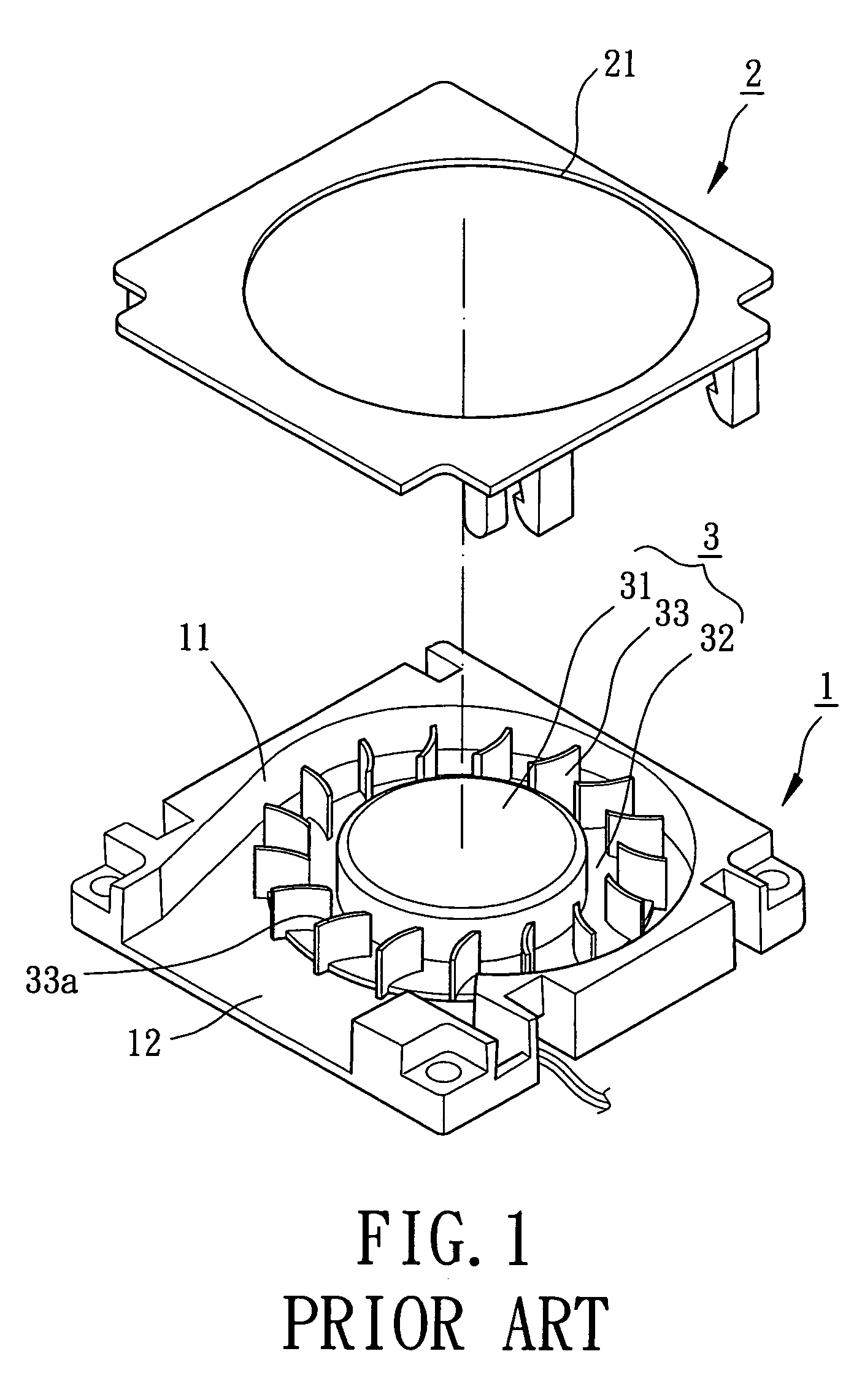
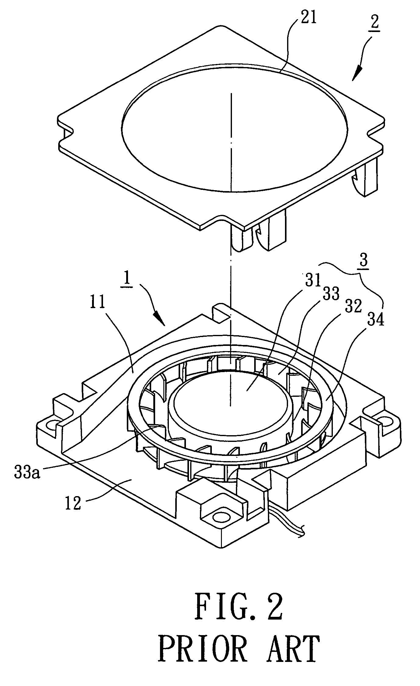
[0027]Referring to FIGS. 3 and 4, an impeller 4 in accordance with the present invention comprises a hub 41, at least one supporting member 42, a plurality of blades 43, and a connecting ring 44. The impeller 4 may be coupled with a motor (not shown) and assembled with a casing 1 and a cover 2 (see FIGS. 1 and 2) to form a complete radial-flow heat dissipating fan. The motor is mounted inside the hub 41 that is rotatably mounted in a compartment 11 in the casing 1. The impeller 4 includes an air inlet side 40a adjacent to the inlet 21 of the cover 2 and a bottom side 40b opposite to the air inlet side 40a. In this embodiment, a plurality of supporting members 42 are provided, with each supporting member 42 being connected between a circumference of the hub 41 and an associated one of the blades 43. Preferably, each supporting member 42 is a wave-like rib extending from the circumference of the hub 41 to the associated blade 43. A connecting ring 44 extends across a bottom edge 43b o...

third embodiment

[0033]FIG. 7 illustrates the invention, wherein the impeller 4 comprises a connecting ring 45 extending across the air inlet side edge 43a of the blades 43, thereby reinforcing the air inlet side 40a of the impeller 4. Further, the connecting ring 45 reduces the risk of inadvertent leakage of radial airflow via the inlet 21.

fourth embodiment

[0034]FIG. 8 illustrates the invention, wherein each of the remaining blades 43 having a higher axial level (see air inlet side edge 43a) includes a stepped section 43c that has an axial level the same as that of the air inlet side edges 43a1 of the blades 43′. The distribution of blades 43, 43′ at the air inlet side 40a of the impeller 4 is sparser than that in the above embodiments, further increasing the air inlet area while providing the lower portion of the blades 43 and the blades 43′ with a greater air driving power.


PUM


Abstract

An impeller for a radial-flow heat dissipating fan includes a hub and a plurality of blades surrounding the hub. The blades are connected to a circumference of the hub to allow joint rotation of the hub and the blades. The impeller includes an air inlet side and a bottom side. Distribution of the blades at the air inlet side of the impeller is sparser than that at the bottom side of the impeller, thereby increasing an air inlet amount.

Description

BACKGROUND OF THE INVENTION[0001]1. Field of the Invention[0002]The present invention relates to an impeller for a radial-flow heat dissipating fan. In particular, the present invention relates to an impeller for a radial-flow heat dissipating fan with increased air inlet amount.[0003]2. Description of Related Art[0004]FIG. 1 of the drawings illustrates a conventional radial-flow heat dissipating fan. The radial-flow heat dissipating fan in FIG. 1 comprises a casing 1 and a cover 2. The casing 1 includes a compartment 11 and a side outlet 12. The cover 2 is mounted to the casing 1 and includes an inlet 21. An impeller 3 is rotatably mounted in the compartment 11 of the casing 1 and includes a hub 31, a supporting member 32 extending from the hub 31, and a plurality of blades 33 each having an edge mounted on a side of the supporting member 32.[0005]FIG. 2 illustrates another conventional radial-flow heat dissipating fan, wherein a connecting ring 34 extends across the other edges of...

Claims


Application Information

Patent Timeline
Patent Type & Authority Patents(United States)
IPC IPC(8): F01D5/22
CPCF04D29/283
Inventor HORNG, ALEXLU, YU-YUANFANG, MEI-CHIH
Owner CHINOOK SCIENCES
Why Eureka
Try Eureka