
Ballast having multiple circuit failure protection and method for ballast circuit protection

a ballast and circuit technology, applied in the field of intelligent ballasts, can solve the problems of inability to connect sensors, complete ballast fails including processing sections, and undesirable to have the processing circuit portion also be without power,

Inactive Publication Date: 2007-04-24
LUTRON TECH CO LLC
View PDF6 Cites 31 Cited by
  • Summary
  • Abstract
  • Description
  • Claims
  • Application Information

AI Technical Summary

Benefits of technology

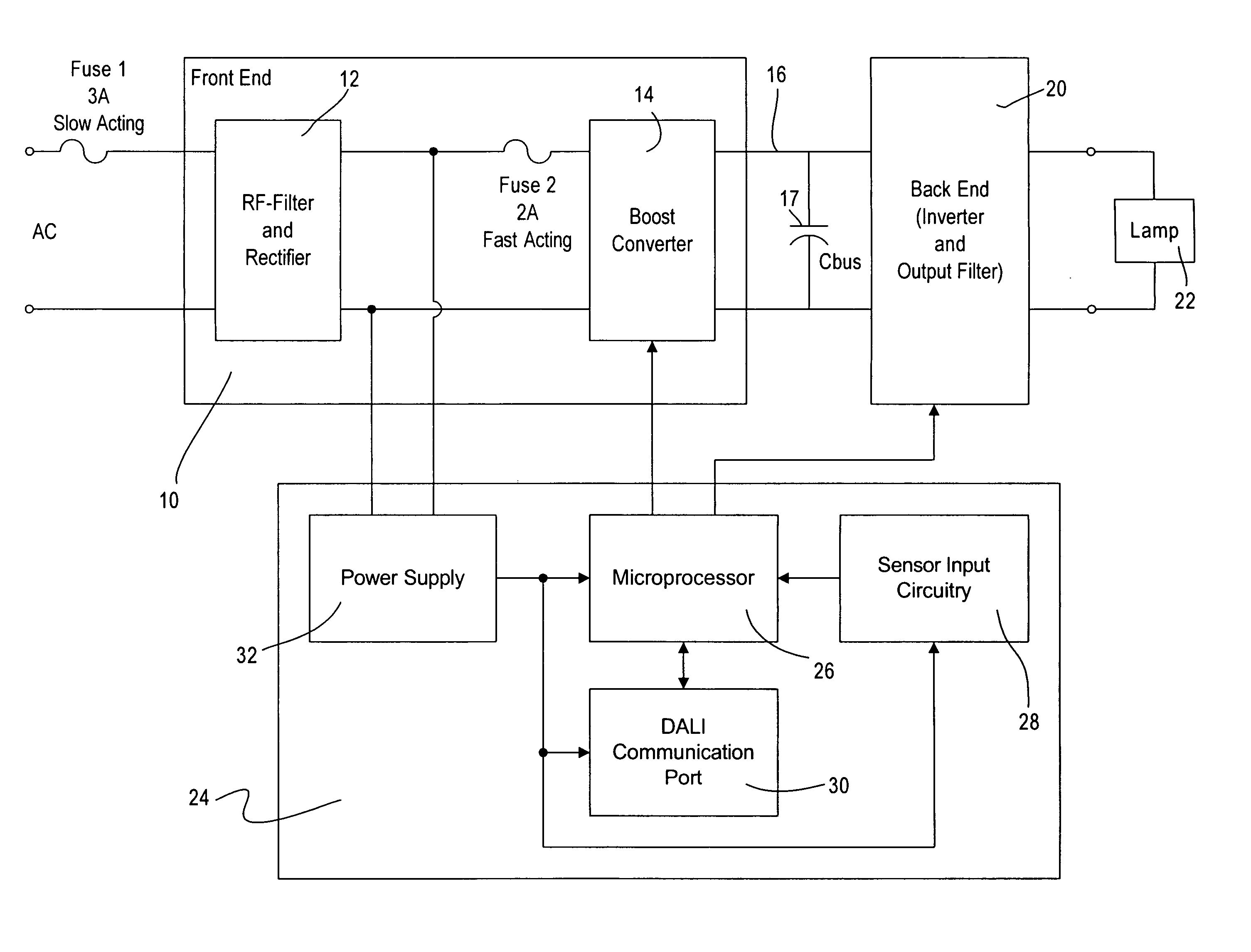
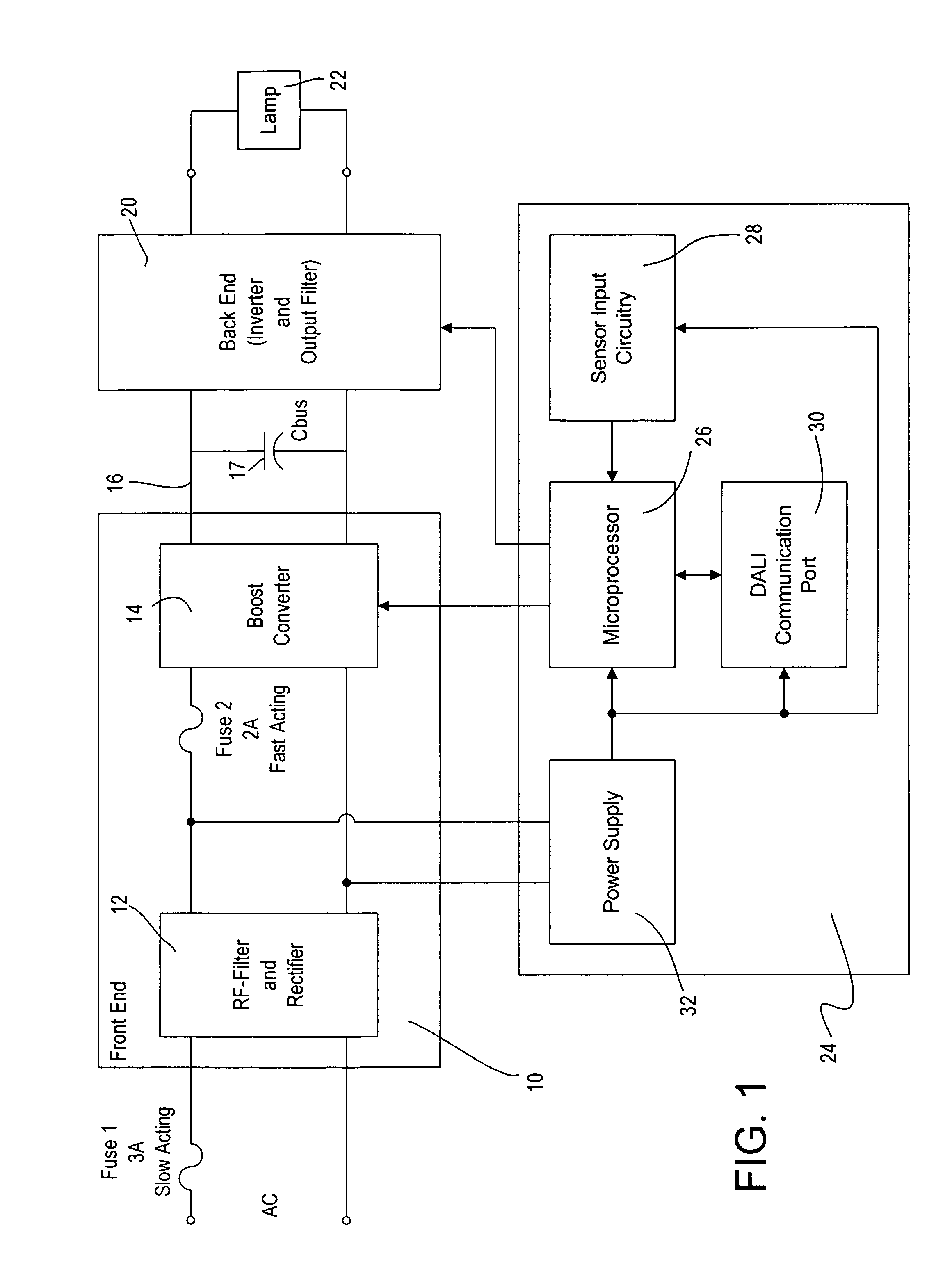
"The invention is a ballast that has two parts: one for supplying power to a lighting load and another for processing data. The first part receives power from an AC main supply and converts it for use by the lighting load. The second part has its own power supply that is protected by a first protection circuit. This circuit prevents overcurrent conditions that could damage the second part. The second part has its own second protection circuit that takes over in case of a failure in the first circuit. This prevents damage to the second part and allows the first part to continue supplying power to the second part."

Problems solved by technology

However, if the ballast fails, and the fuse blows, the entire ballast fails including the processing section.
This presents a problem because in the processing section handles incoming information from attached sensors and communicates this information to the communication link via the communication port for use by other system components.
If the ballast fails and the fuse blows as a result of a fault in the power circuit section, it is undesirable to have the processing circuit portion also be without power.
If the processing section is without power, then the information from any connected sensors is no longer available to the rest of the system.
Thus, a single ballast failure in the power circuit portion can have far reaching consequences to the system if the ballast that fails is one that has a sensor connected to it.

Method used


Image

  • Ballast having multiple circuit failure protection and method for ballast circuit protection
  • Ballast having multiple circuit failure protection and method for ballast circuit protection
  • Ballast having multiple circuit failure protection and method for ballast circuit protection

Examples


first embodiment

[0013]With reference now to the drawings, FIG. 1 is a block diagram of a ballast according to the present invention. As described above, the ballast includes a power circuit section 8 having a front end or input section 10, a DC bus 16 having a bus capacitor 17 coupled thereacross, and a back end or output section 20 that supplies a lamp load 22 with power. The front end 10 includes an RF filter and rectifier 12 and a boost converter 14 and the back end includes an inverter and an output filter. Note that the boost converter can be any type of active or passive power factor correcting circuit. The ballast also includes a processing section 24 including a microprocessor 26, sensor input circuitry 28 that receives inputs from external sensors such as occupancy sensors, photosensors, and infrared sensors, as well as other inputs from the power circuit section 8 of the ballast itself to monitor and control the operation of the ballast. The microprocessor 26 is also connected to a commun...

fourth embodiment

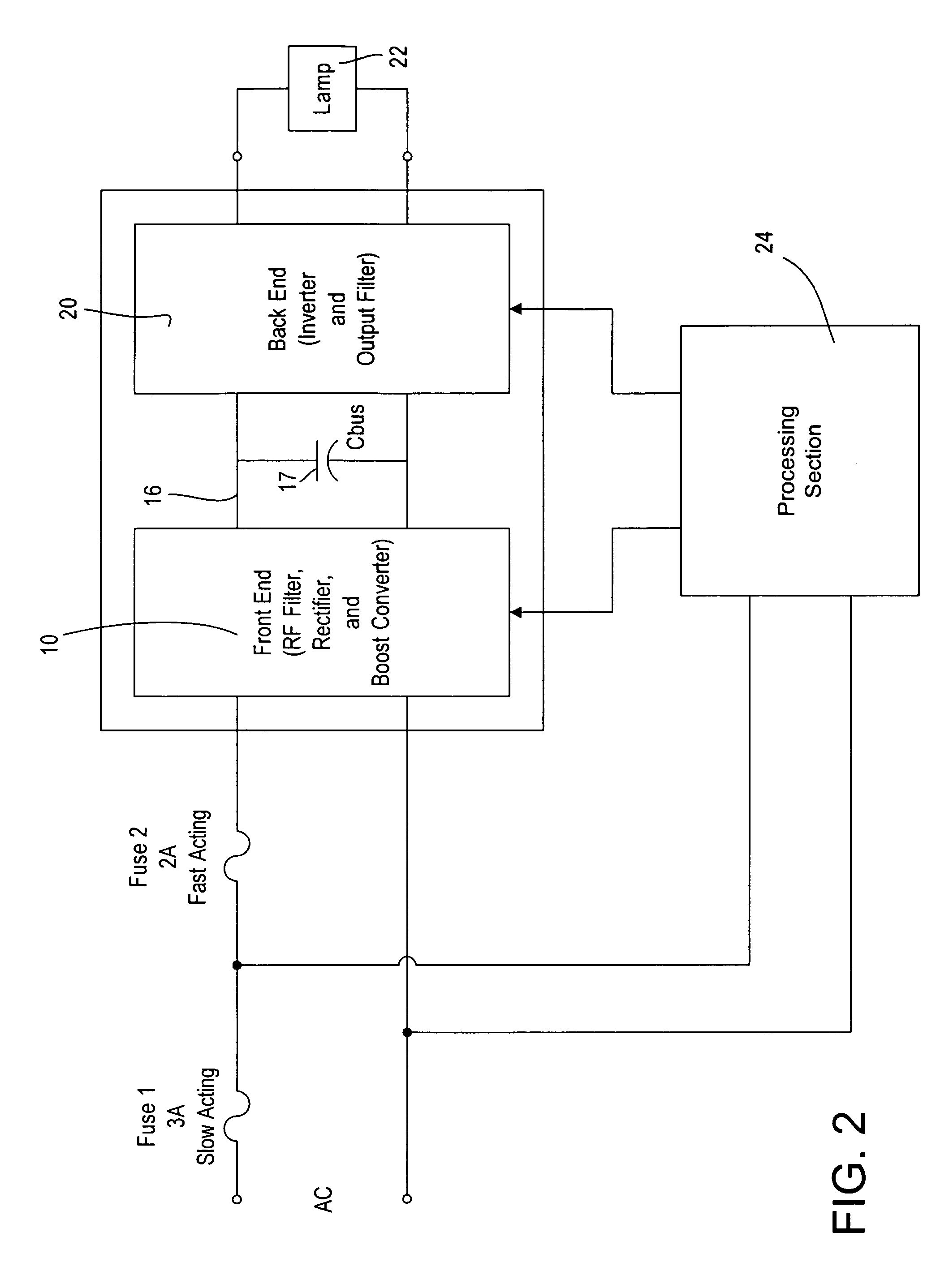
[0022]FIG. 3 and FIG. 4 show block diagrams of a third and the protected ballast, respectively.


PUM


Abstract

A ballast for a gas discharge lamp comprising a first circuit portion for providing power to a lighting load and a second circuit portion for processing data exchanged with a communication link, the first circuit portion receiving power from an AC main supply for conversion to a form suitable to supply power to the lamp, and the second circuit portion having a power supply supplied from the AC main supply, the power supply being coupled at the input of the AC main supply to the first circuit portion, further comprising a first protection circuit coupled in series with the AC main supply for protecting the first and second circuit portions in the event of an electrical circuit failure leading to an overcurrent condition, the power supply for the second circuit portion being coupled such that it is protected by the first protection circuit; further comprising a second protection circuit disposed in series with the first circuit portion and providing protection only in the event of electrical failure leading to an overcurrent condition in the first circuit portion; the second protection circuit adapted so that in the event of electrical failure in the first circuit portion, the second protection circuit will discontinue the supply of current to the first circuit portion, thereby preventing an overcurrent in the first protection circuit that would cause the first protection to interrupt current, and thereby allowing the first protection circuit to continue to supply electrical current to the second circuit portion.

Description

BACKGROUND OF THE INVENTION[0001]The present invention relates to power supplies, an in particular, to an intelligent ballast for powering a lighting load, for example a gas discharge lamp such as a fluorescent lamp. The present invention relates to ballasts of the type disclosed in the Assignee's U.S. patent application Ser. No. 10 / 824,248 filed Apr. 14, 2004 and entitled Multiple-Input Electronic Ballast With Processor, the entire disclosure of which is incorporated herein by reference.[0002]In the ballast disclosed in the above-identified pending patent application, the ballast includes an input or front end power circuit section that includes an RF filter and rectifier and a valley fill circuit including an energy storage capacitor, for providing a DC bus voltage. The DC bus voltage is provided to a back end or output stage including an inverter and an output filter. In the back end, an inverter is driven to provide a high frequency AC output voltage that is filtered by an outpu...

Claims


Application Information

Patent Timeline
Patent Type & Authority Patents(United States)
IPC IPC(8): G05F1/00
CPCH05B41/2856Y10S315/07
Inventor MOSEBROOK, DONALD R.VESKOVIC, DRAGAN
Owner LUTRON TECH CO LLC
Learn More