
Probe card

a technology of probes and cards, applied in the field of probes, can solve the problems of difficult advancement in complexity in the integrated circuit of measurement objectives, the inability of the probe to endure a load, etc., and achieve the effect of improving the strength of the probe, and reducing the friction coefficien

Inactive Publication Date: 2007-04-24
NIHON DENSHIZAIRYO
View PDF14 Cites 3 Cited by
  • Summary
  • Abstract
  • Description
  • Claims
  • Application Information

AI Technical Summary

Benefits of technology

The present invention provides an arch type probe and a probe card that can withstand overdriving and still maintain their functionality. The arch type probe is designed to have a load-bearing capacity and can be made smaller in size. The probe card includes the arch type probe and a reinforcing member or a reinforcing member with higher elasticity than the probe. The arch type probe can be coated with a material to increase its strength or to reduce friction between the probe and the base plate. The reinforcing member can be integrated with the arch type probe or added separately. These improvements make the arch type probe and probe card more durable and reliable for use in advanced integrated circuit measurement.

Problems solved by technology

If a needle-like probe is miniaturized, however, the probe cannot endure a load caused by overdriving and is broken.
This causes advancement in complexity in a integrated circuit of a measurement objective to be difficult.

Method used


Image

  • Probe card
  • Probe card
  • Probe card

Examples


Embodiment Construction

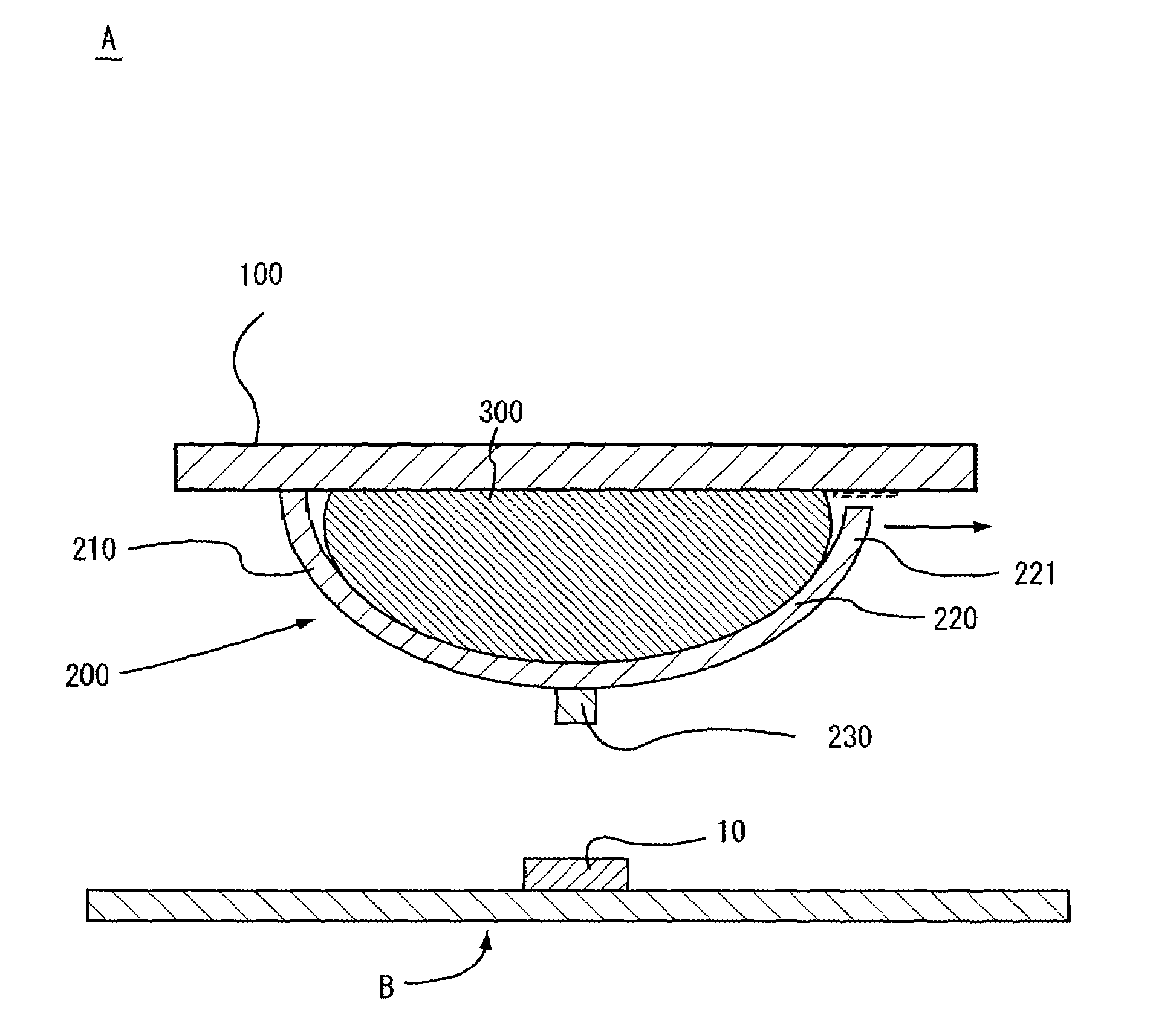
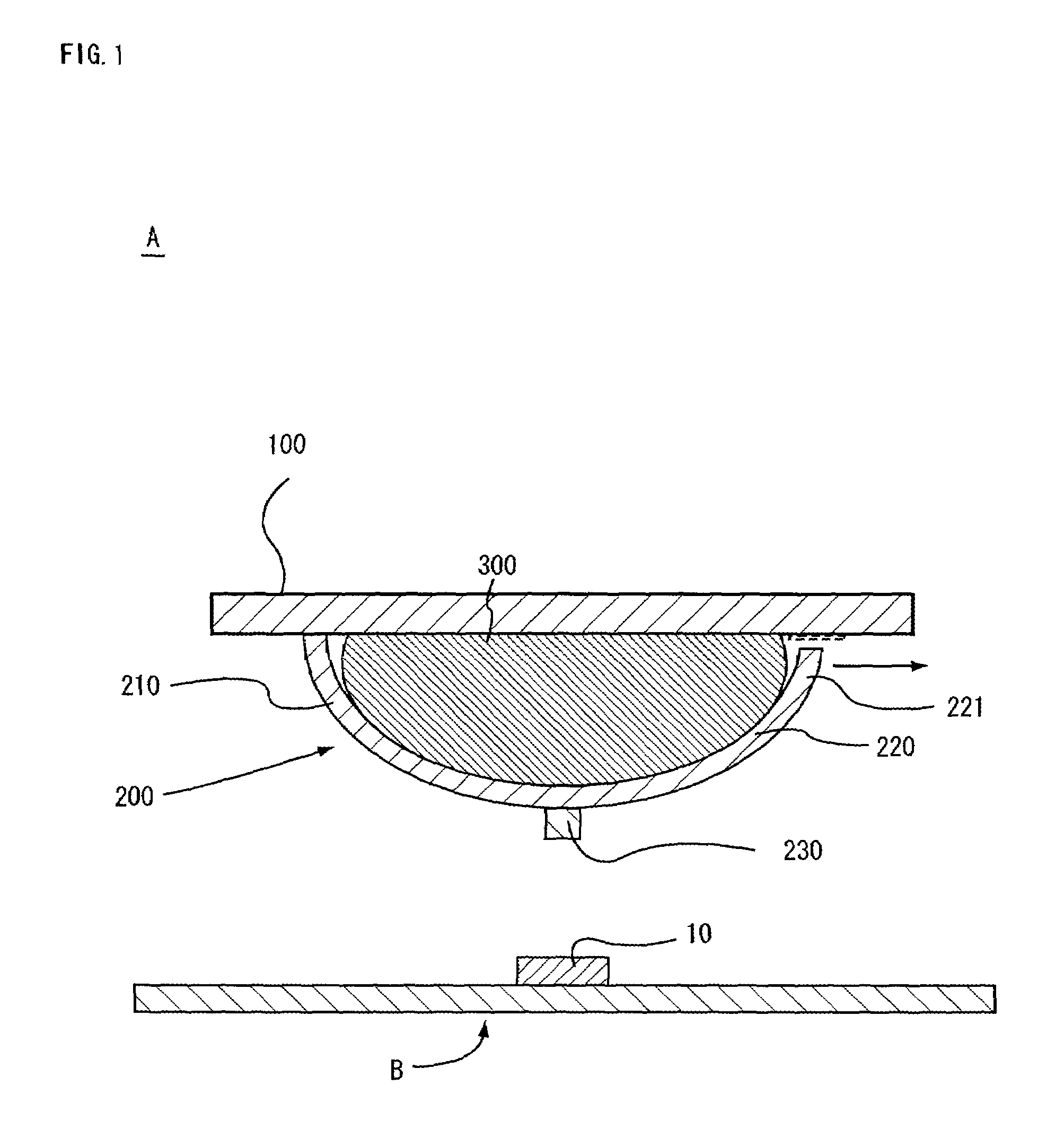
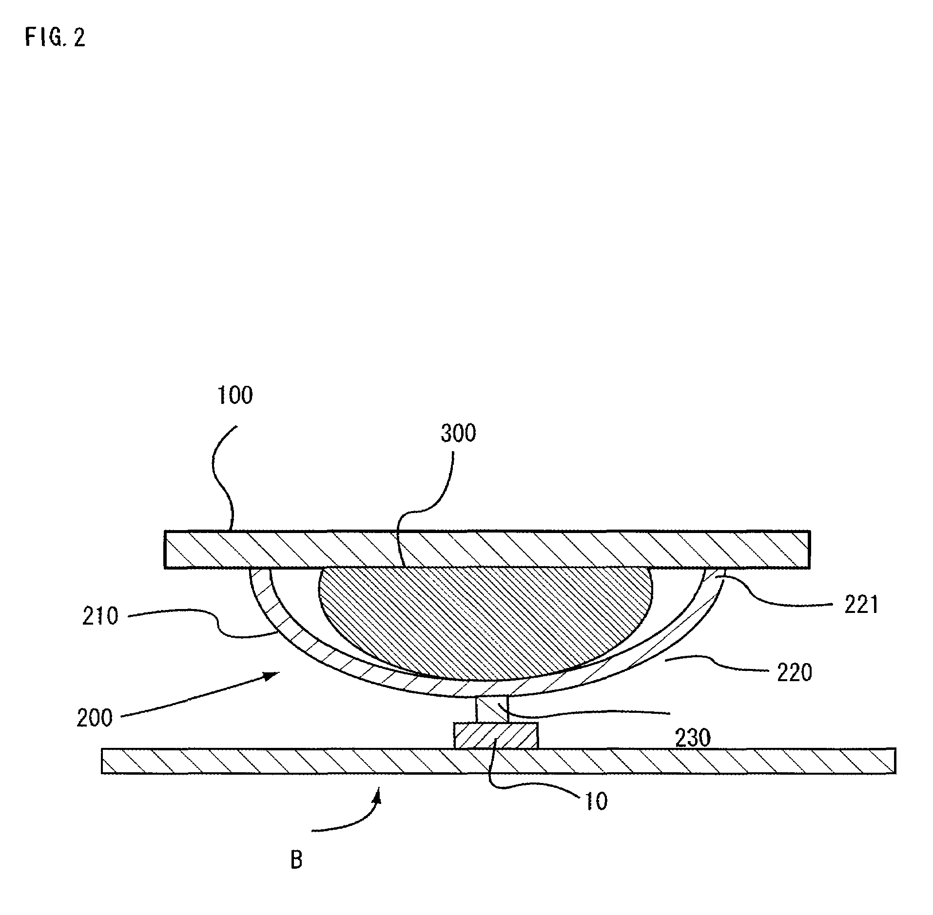
[0027]Description will be given of a probe card using an arch type probe related to an embodiment of the present invention below. FIG. 1 is a model sectional view of a probe card using an arch type probe related to an embodiment of the present invention, FIG. 2 is a model sectional view showing a usage state of the probe card, FIG. 3 is a model view of a second quarter circle arc portion of an arch type probe of the probe card, the distal end portion of which second quarter circle arc portion is spherical and FIG. 4 is a model view for describing a reinforcing member for an arch type probe of the probe card, which member is different from the arch type probe.

[0028]A probe card A shown in FIG. 1 is a sensing section of a measuring instrument, not shown, for a measurement objective B and has a base plate 100 held by a prober of the measuring instrument, and thereby disposed opposite the measurement objective B and plural arch type probes 200 formed on a surface of the base plate 100. ...


PUM


Abstract

It is an object of the present invention to provide an arch type probe capable of enduring a load caused by overdriving even if the probe is miniaturized, and a probe card using the same. An arch type probe 200 has a shape including a first quarter circle arc portion 210 which is supported at one end thereof by the base plate 100 and a second quarter circle arc portion 220 which is connected to the other end of the first quarter circle arc portion 210, extending toward the base plate and a little shorter than the first quarter circle arc portion 221. The top portion of the arch type probe 200 serves as a contact surface brought into contact with an electrode of a semiconductor water B.

Description

BACKGROUND OF THE INVENTION[0001]1. Field of the Invention[0002]The present invention relates to a probe used in measurement of electric characteristics of a measurement objective, and a probe card using the same.[0003]2. Prior Art[0004]There has been available a probe card of this kind having needle-like probes brought into contact with electrodes of a measurement objective and a base plate on which the probes are provided, wherein the probes are brought into contact with the electrodes, thereafter pressed against them (overdriven), thereby securing a predetermined contact pressure of the probes, while on the other hand, the probes are caused to slide on surfaces of the electrodes sideways (scrubbing is caused to occur), thereby realizing electric conduction between the probes and the electrodes (see Patent literature 1).[0005]Patent literature 1 is JP-A No. 2001-41978.[0006]In a probe card, a measurement objective in the recent years has been advanced in complexity in an integrate...

Claims


Application Information

Patent Timeline
Patent Type & Authority Patents(United States)
IPC IPC(8): G01R31/00G01R31/02G01R31/28G01R1/067G01R1/073H01L21/66
CPCG01R1/06733G01R1/07357G01R1/0735H01L22/00
Inventor MINE, ATSUSHIFURUSHO, TORANOSUKEMACHIDA, KAZUMICHIURATA, ATSUOKIMURA, TEPPEISAKATA, TERUHISA
Owner NIHON DENSHIZAIRYO
Learn More