Antenna for portable communication device equipped with a hinge

a communication device and hinge technology, applied in the direction of transmission, substation equipment, radiating element structure forms, etc., can solve the problems of preventing useful radiation, requiring a substantial space inside the antenna, and sensitive to folding and unfolding, so as to improve the broadband performance of the whole antenna and improve efficiency

Inactive Publication Date: 2007-04-24
SONY ERICSSON MOBILE COMM AB
View PDF15 Cites 59 Cited by
  • Summary
  • Abstract
  • Description
  • Claims
  • Application Information

AI Technical Summary

Benefits of technology

[0008]The present invention is directed towards solving the problem of providing an antenna that does not protrude from any of the parts of a portable communication device having two parts joined to each other by a hinge and that lets a first antenna element be as large as possible for better efficiency, while at the same time providing better broadband performance of the whole antenna.
[0009]One object of the present invention is thus to provide a portable communication device having two parts joined to each other by a hinge and including an antenna that does not protrude from any of the parts of a portable communication device and lets a first antenna element be as large as possible for better efficiency, while at the same time providing better broadband performance for the whole antenna.
[0034]Another object of the present invention is directed towards providing an antenna arrangement for a portable communication device having two parts joined to each other by a hinge element, where the antenna does not protrude from any of the parts and lets a first antenna element be as large as possible for better efficiency.
[0038]The invention has the following advantages. It allows the first antenna element to be made as large as possible while at the same time not having any protruding bulky parts, since the second antenna element is placed in the hinge element. It also provides good broadband properties. The antenna can be provided in a phone where one part has two sections that can be twisted in relation to each other. The antenna according to the invention will not hinder such twisting or have its efficiency degraded by such twisting.

Problems solved by technology

These antennas require a substantial space inside the phone and are sensitive to folding and unfolding.
If placed on a twistable upper half, usually containing the main display, such a PIFA will be turned to the inside of the part of the phone, preventing any useful radiation.
Since the antenna is protruding from the phone body, it makes the phone larger and more bulky than it has to be, especially when folded.

Method used


Image

  • Antenna for portable communication device equipped with a hinge
  • Antenna for portable communication device equipped with a hinge
  • Antenna for portable communication device equipped with a hinge

Examples


first embodiment

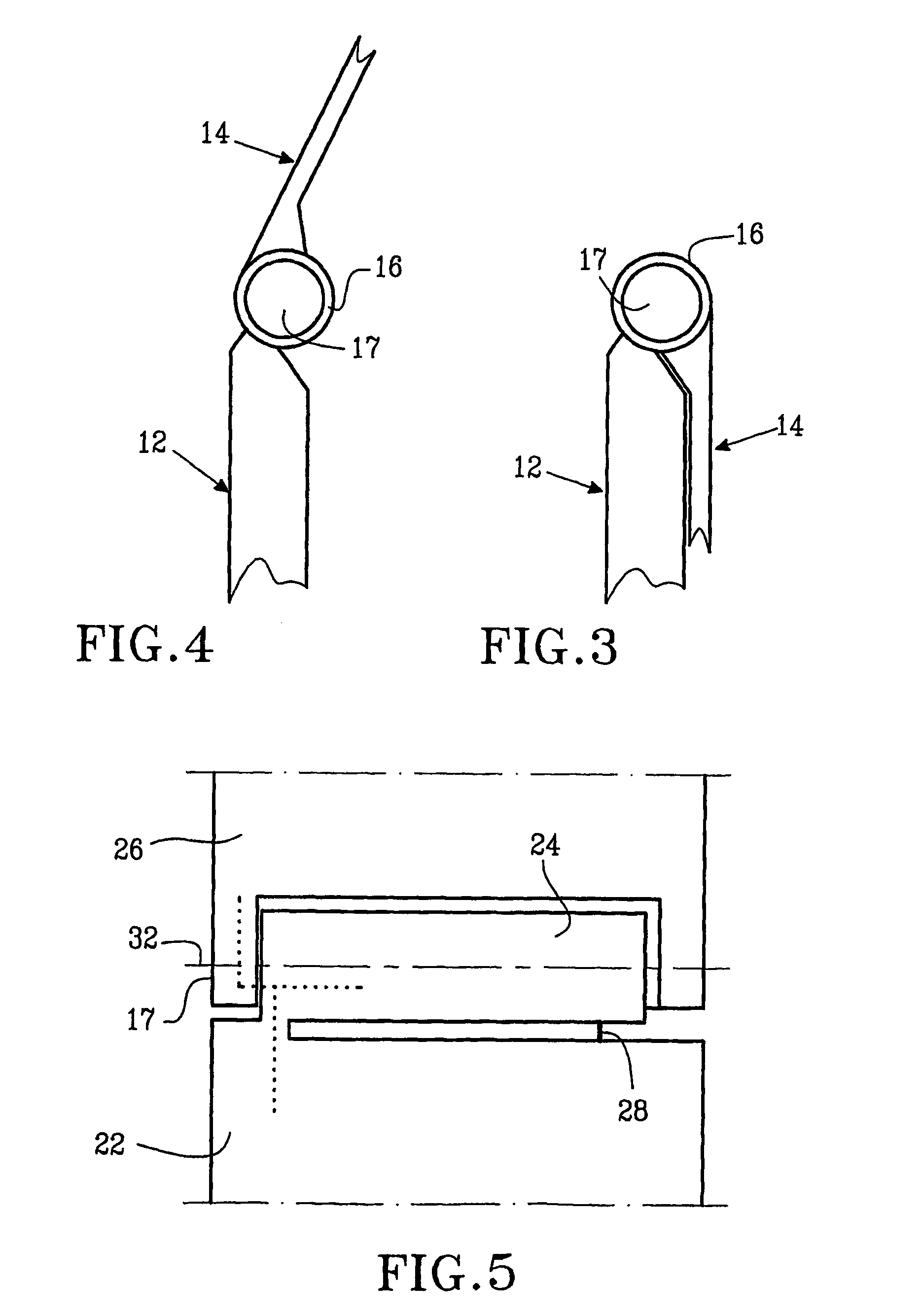
[0055]FIG. 5 schematically shows a top view of the antenna elements in the hinging section of the clamshell phone according to the invention, when the phone is in an open position. The antenna includes a first antenna element 22 provided in the first part, which is electrically connected to a second cylindrical antenna element 24 at the first end. The second antenna element is provided in the interior of the hinge element and is preferably hollow. The second antenna element 24 as well as the hinge element extend along the entire end of the phone and a third antenna section 26 is provided in the second part of the phone and is electrically connected to the second antenna element 24 at the first end 17 of the hinge element. The second antenna element 24 has a second end located at a second end of the hinge element. This end is not electrically connected to the first and third antenna elements 22 and 26, and thus a first gap is provided between the first and second antenna elements 22 ...

second embodiment

[0060]FIG. 8 schematically shows a top view of antenna elements in a clam-shell phone according to the invention, when the phone is in an open position. Here the second part of the phone is divided into a first section connected to the hinge element and a second section connected to the first section. The first section is provided with hinging means providing a second axis 38 around which the second section of the second part can be rotated. The second axis 38 is provided essentially at right angles to the first axis 32. The third antenna element is therefore here divided into a first section 34 provided in the first section of the second part of the phone and connected to the second antenna element 24 and a second section 36 provided in the second section of the second part of the phone and arranged to rotate around the second axis 38. The first and second sections 34 and 38 of the third antenna element have a continuous contact over the entire interface between the first and secon...

third embodiment

[0061]FIG. 9 schematically shows a top view of antenna elements in a clam-shell phone according to the invention, when the phone is in an open position. Here the second and third antenna elements are electrically connected by breakable electrical contacts along the entire interface between the second and third antenna elements. This means that there are electrical connections between the second and third antenna elements all along the hinge element when the phone is in the open position. Thus there is no gap between the first section of the third antenna element and the second antenna element. Therefore the second antenna element can be seen as including the third antenna element, having a first part 40 including the first axis 32 and a second part 36 rotatable round the second axis. Also here the rotation round the second axis 38 has no or little influence on the performance of the antenna. Because the second antenna element now is much larger, it provides a substantial part of the...


PUM


Abstract

A portable communication device includes a first part including a first antenna element located within and extending through a portion of the first part and radio circuit feeding antenna elements, a second part hingedly joined to an end of the first part for providing at least one open and one closed position of the phone, and a hinge element connected to the first and second parts. The hinge element stretches along the end of the first part for providing rotation of one part in relation to the other part around a first axis having a first and second end. The hinge element includes a second antenna element. The radio circuit is connected between the first and second antenna elements.

Description

RELATED APPLICATIONS[0001]The present application is a 35 U.S.C. §371 national phase application of PCT International Application No. PCT / EP2003 / 013001, having an international filing date of Nov. 20, 2003, and claiming priority to European Patent Application No. 02026232.5, filed Nov. 26, 2002, and U.S. Provisional Application No. 60 / 431,505, filed Dec. 4, 2002, the disclosures of which are incorporated herein by reference in their entireties. The above PCT International Application was published in the English language and has International Publication No. WO 2004 / 049502 A1.TECHNICAL FIELD OF THE INVENTION[0002]The present invention relates to the field of antennas and more particularly to a portable communication device with a hinge including an in-built antenna as well as an antenna arrangement for a portable communication device, which includes a hinge.DESCRIPTION OF RELATED ART[0003]There is a trend within the filed of portable communicating devices, and especially within the ...

Claims


Application Information

Patent Timeline
Patent Type & Authority Patents(United States)
IPC IPC(8): H01Q1/24H04B1/38H04M1/02
CPCH01Q1/242H01Q1/243H04B1/3833H04M1/0212H04M1/0216H01Q1/24H04B1/38H04M1/02
Inventor LINDELL, BO
Owner SONY ERICSSON MOBILE COMM AB
Why Eureka
Try Eureka