Method of making a medical grasper

a grasper and medical technology, applied in the field of medical graspers, can solve the problems of inability to miniaturize the disclosed construction into a three-french, inconvenient, and elongated tubular configuration of the ureter,

Active Publication Date: 2007-05-01
COOK UROLOGICAL +1
View PDF4 Cites 39 Cited by
  • Summary
  • Abstract
  • Description
  • Claims
  • Application Information

AI Technical Summary

Benefits of technology

[0004]An object of the invention is to fulfill the need expressed above. In accordance with the principles of the present invention, this objective is achieved by providing a method of forming an annularly expanding and retracting gripping and releasing mechanism suitable for use as a stone grasper. The gripping and releasing mechanism comprises an annular array of fixed flexure elements fixed together at proximal ends thereof and corresponding movable flexure elements fixed with respect to distal ends of respective fixed flexure elements and movable within respective adjacent fixed flexure elements. This method enables movement of the movable flexure elements outwardly of the fixed flexure elements which causes the fixed flexure elements to flex transversely outwardly and create an expanded condition. This expanded condition is defined by an annular series of transversely outwardly flexed fixed flexure elements interconnected by an annular series of arcuately flexed portions of the movable flexure elements. The grasper also enables movement of the movable flexible elements when in an expanded condition in a direction inwardly of the fixed flexure elements which causes the expanded condition to progressively retract.

Problems solved by technology

While the disclosed configurations of the '622 patent when made with relatively large dimensions are satisfactory, difficulties occur in attempting to miniaturize the disclosed constructions into a three French size such as required by many popular scopes.
These size restrictions create an especially troublesome problem in providing a cost effective construction and method for making the gripping and releasing mechanism embodied in a medical device suitable for both extracting stones directly from the kidneys as well as extracting stones from the ureter.
This is because of the chamber configuration of the kidneys, which make the usual closed pointed end of a urethral basket, which operates in the elongated tubular configuration of the ureter, inappropriate.
The heart of the problem lies in the construction and method used to accomplish the connection between each movable flexure element and the distal end of a corresponding fixed flexure element.

Method used


Image

  • Method of making a medical grasper
  • Method of making a medical grasper
  • Method of making a medical grasper

Examples


Embodiment Construction

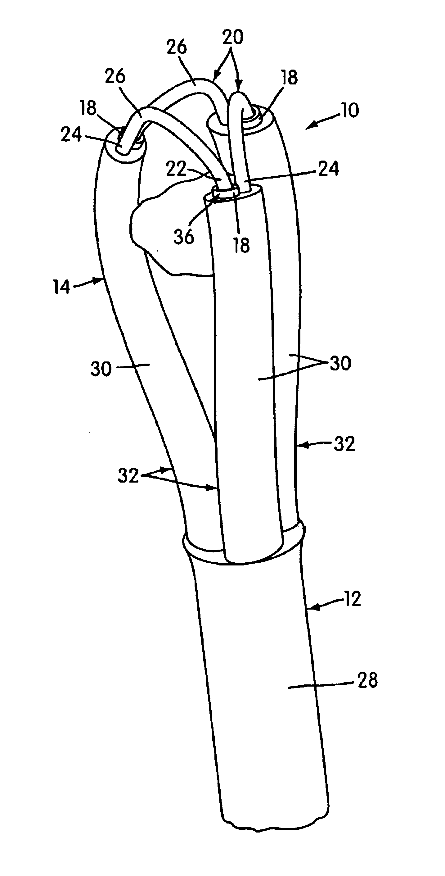
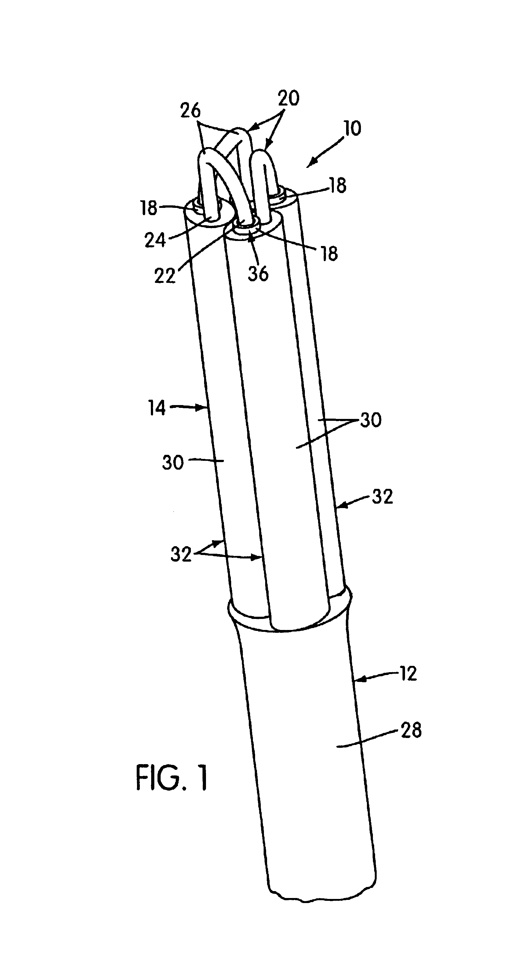
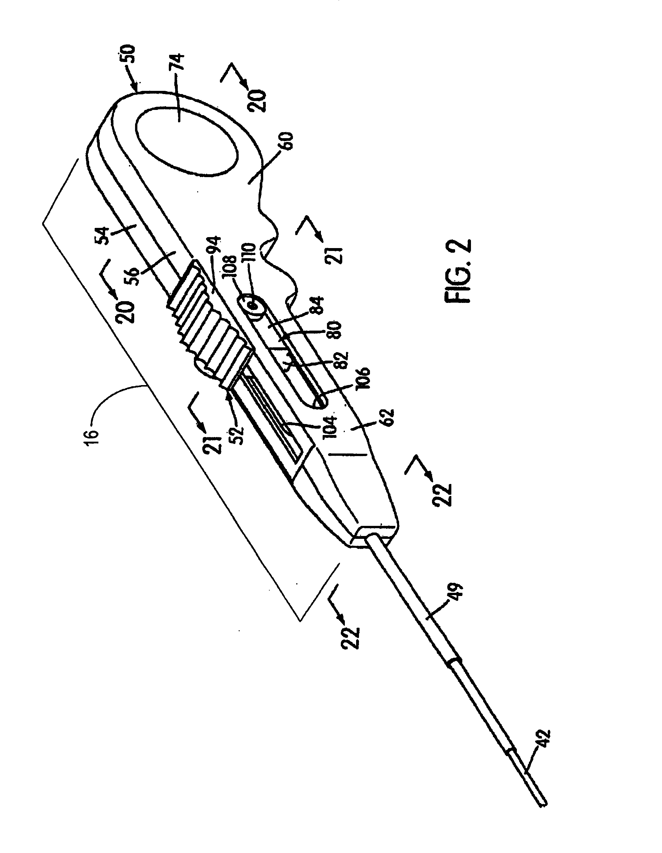
[0032]Referring now more particularly to the drawings, there is shown therein a medical grasper, generally indicated at 10, embodying the principles of the present invention. The medical grasper 10 as shown includes, in general, an elongated cannula assembly, generally indicated at 12, having an expandable and retractable gripping and releasing mechanism, generally indicated at 14, on the distal end thereof and a moving handpiece assembly, generally indicated at 16, on the proximal end thereof. The moving assembly 16 is manually operable to expand and retract the gripping and releasing mechanism 14. As shown, the cannula assembly 12 of the medical extractor 10 is capable of being inserted through the central passage of a conventional scope deployed within a patient with the gripping and releasing mechanism 14 extending within the patient outwardly of the distal end of the scope and the moving assembly 16 disposed inwardly of the proximate end of the scope exteriorly of the patient. ...


PUM

PropertyMeasurementUnit
angleaaaaaaaaaa
angleaaaaaaaaaa
flexibleaaaaaaaaaa

Abstract

A method of forming an annularly expanding and retracting gripping and releasing mechanism providing a series of flexible tubes, comprising providing (1) a series of flexible tubes, (2) a corresponding series of wires, each of which includes a movable wire section and relatively short fixed wire section integrally connected with one end of the movable wire section by a kink configured so that the wire sections extend in longitudinally coextensive relation therefrom; (3) a series of tubular elements of thermoplastic material; and (4) a series of heat shrinkable sleeves assembling a distal end portion of each flexible tube with a fixed wire section, a tubular element and a heat shrinkable sleeve so that the fixed wire section extends along the exterior periphery of the flexible tube with the kink disposed outwardly of the distal end thereof. The tubular element is disposed in surrounding relation to the fixed wire section and the flexible tube and the heat shrinkable sleeve is disposed in surrounding relation to the tubular element. The method further comprises applying heat to the exterior of each heat shrinkable sleeve at a temperature sufficient to contract the sleeve and soften the thermoplastic material of the tubular element surrounded thereby so that the contraction of the sleeve molds the softened thermoplastic material into adhered contact with the exterior surfaces of the surrounded fixed wire section and flexible tube.

Description

CROSS REFERENCE TO RELATED APPLICATIONS AND PATENTS[0001]The present application claims priority from provisional application 60 / 386,190, filed May 28, 2002, the disclosure of which is hereby incorporated by reference into the present specification. The subject matter of the application relates to improvements in medical extractors or graspers of the type disclosed in U.S. Pat. No. 5,906,622, the disclosure of which is hereby incorporated by reference into the present specification.BACKGROUND OF THE INVENTION[0002]The extractor disclosed in the '622 patent comprises an elongated cannula assembly having an annularly expanding and retracting gripping and releasing mechanism at the distal end thereof and a moving assembly at the proximal end thereof. The gripping and releasing mechanism includes an annular series of longitudinally fixed flexure elements and a corresponding series of longitudinally movable flexure elements. The moving assembly is operable to effect a relative movement b...

Claims


Application Information

Patent Timeline
Patent Type & Authority Patents(United States)
IPC IPC(8): A61B17/22B23P11/02
CPCA61B17/221A61B2017/2212Y10T29/49865Y10T29/49927A61B2017/2215
Inventor LIPPITT, ROBERT G.LIPPITT, RAYMOND F.LEOPOLD, ANDREW R.
Owner COOK UROLOGICAL
Why Eureka
Try Eureka