
Device for wrapping a napkin about silverware and associated method

a technology for wrapping napkins and silverware, applied in the field of wrapping devices, can solve the problems of limited apparatus, labor costs in the tens of thousands of dollars annually per restaurant, and inconvenient preparation, and achieve the effect of effectively extracting and effectively generating

Inactive Publication Date: 2007-05-01
AHMED IBRAHIM A +1
View PDF12 Cites 54 Cited by
  • Summary
  • Abstract
  • Description
  • Claims
  • Application Information

AI Technical Summary

Benefits of technology

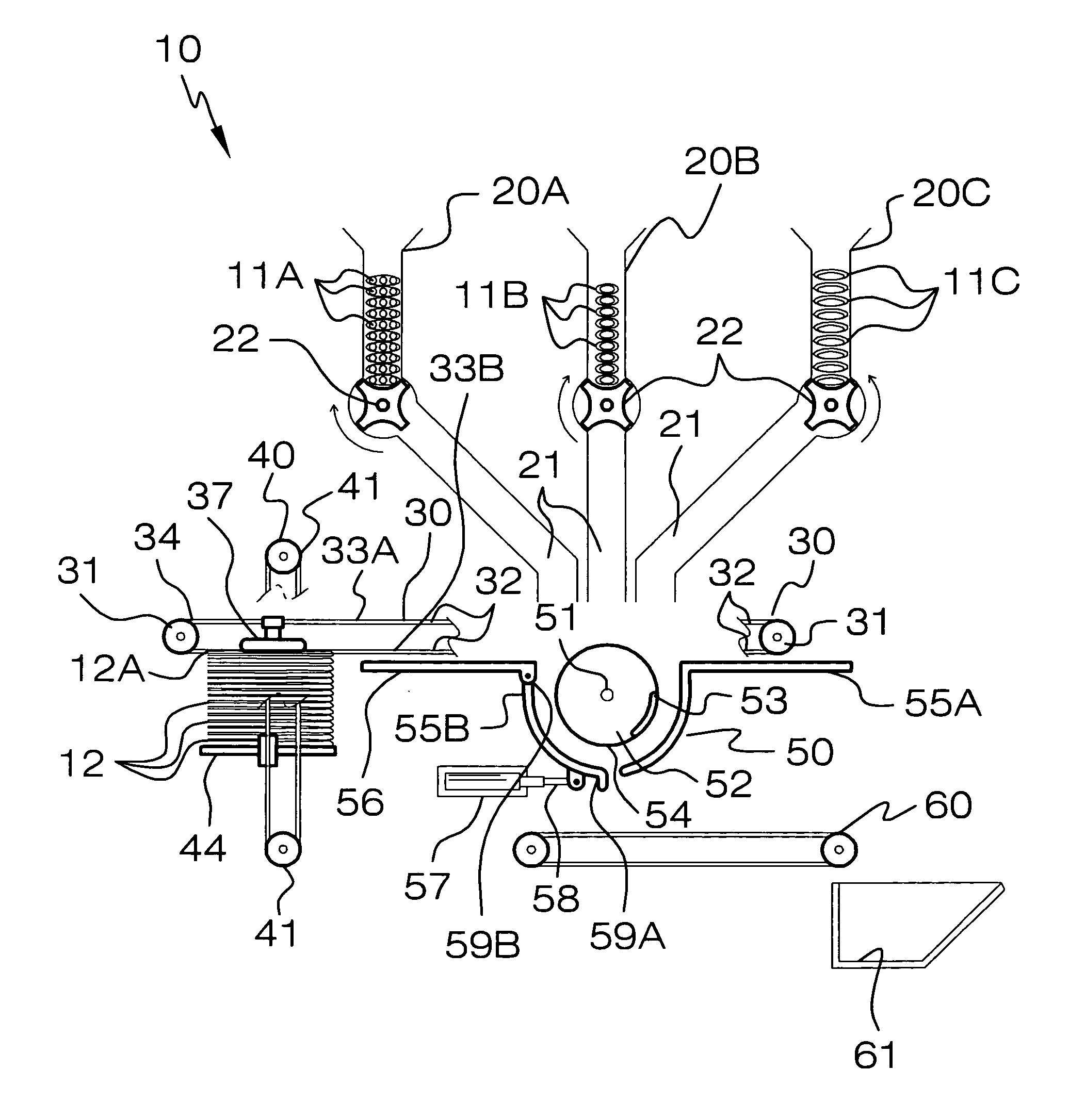
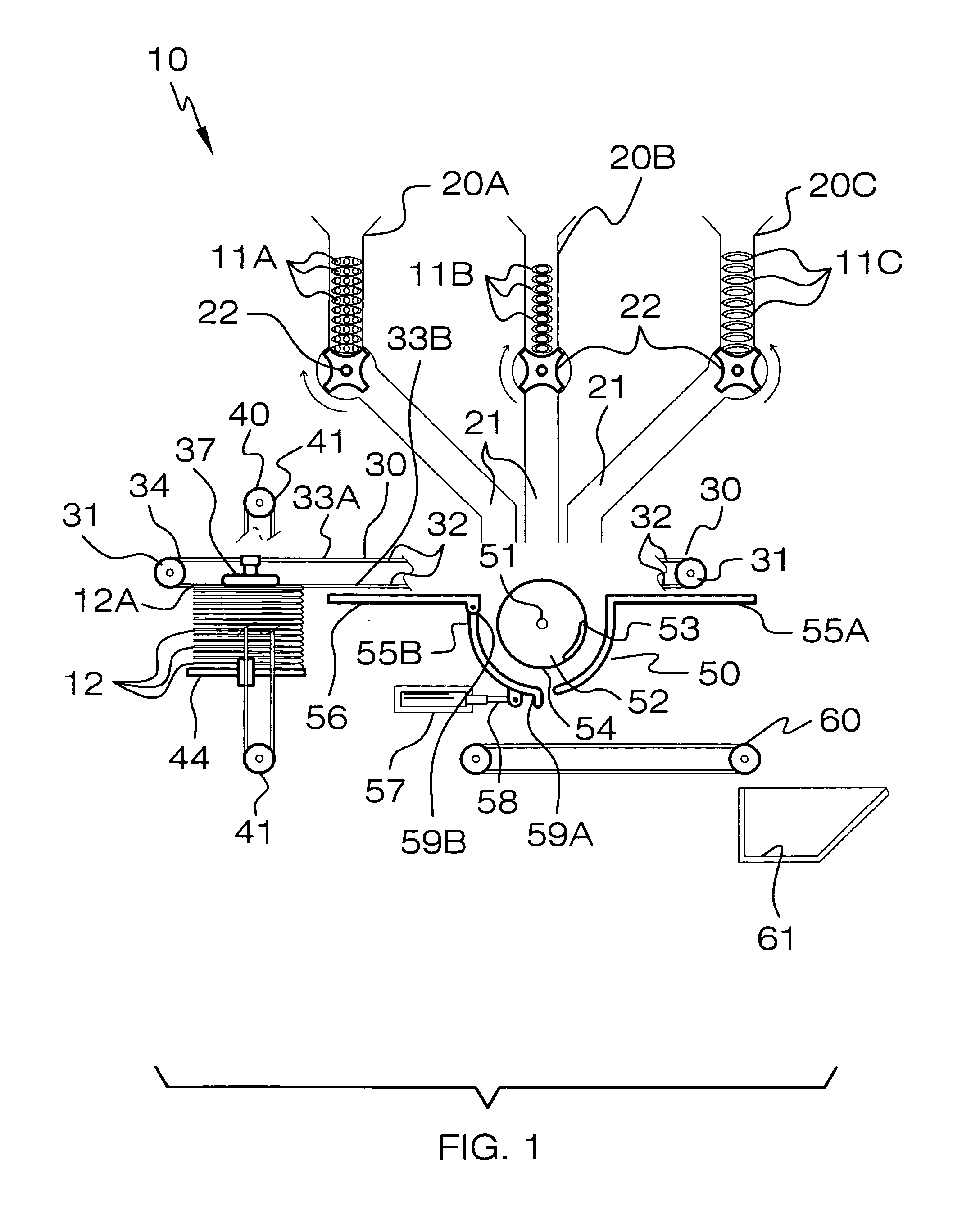
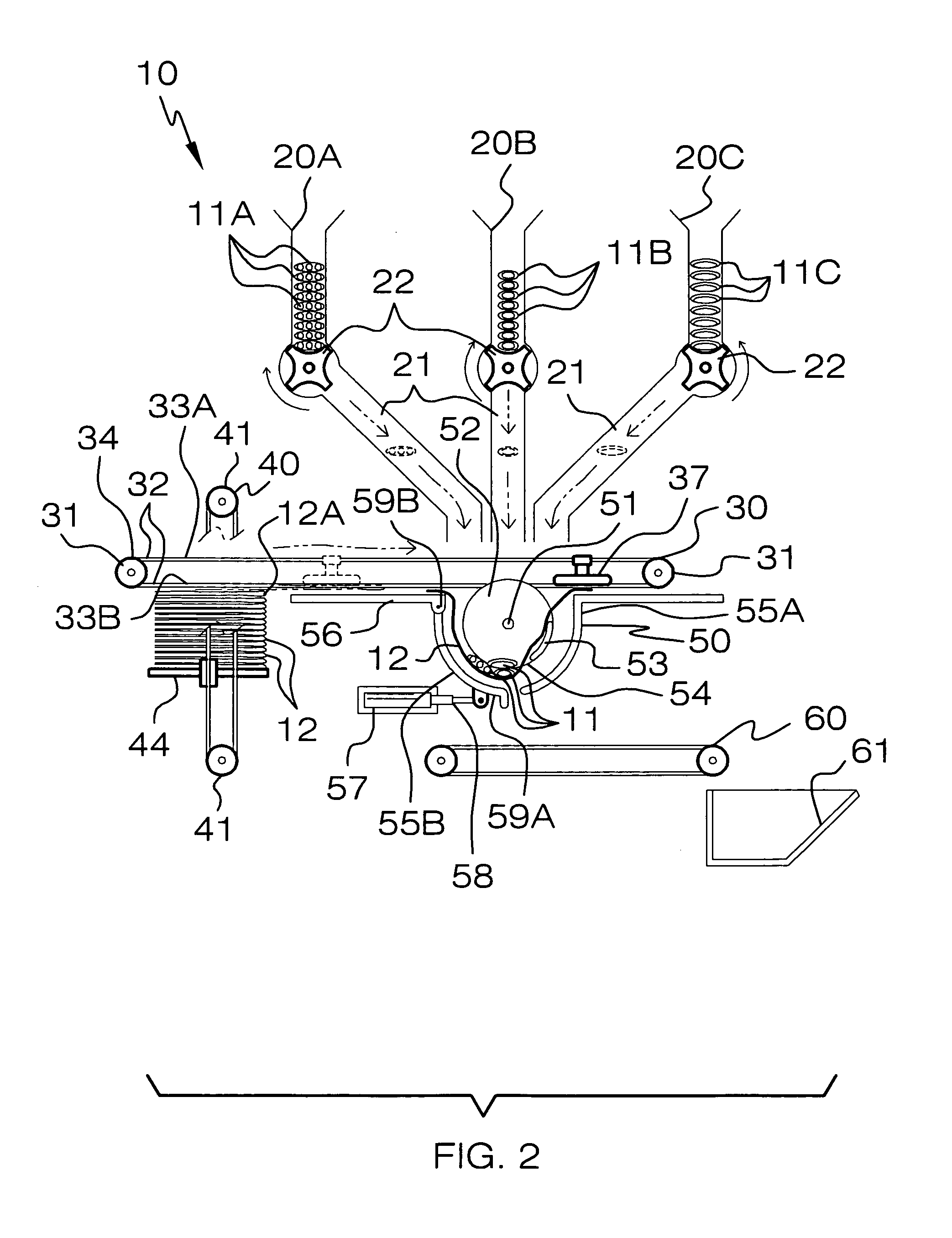
[0015]A vacuum head is operably connected directly to the conveyor belt assembly and intercalated between the top and bottom sections of the unitary belt. Such a vacuum head maintains a static relationship therewith so that the vacuum head horizontally travels in sync with the conveyor belt assembly. The vacuum head is situated above a top napkin of the napkin stack and effectively transfers the top napkin across the conveyor belt assembly where the top napkin is deposited at the unitary area before the eating utensils are released from the hoppers. A motor is in fluid communication with the vacuum head for conveniently and effectively extracting a predetermined volume of air away therefrom during operating conditions.
[0016]A mechanism is included for simultaneously folding the napkin and horizontally registering the eating utensils in a stacked relationship such that the napkin conveniently and effectively becomes folded about the eating utensils before being ejected from the simultaneous folding mechanism. Such a simultaneous folding mechanism preferably includes a central rod transversely oriented to the conveyor belt assembly and situated therebelow. A cylindrical drum is journaled about the rod and includes an arm monolithically formed with an outer edge thereof. A stationary rail has an arcuate shape outwardly spaced from the drum. A dynamic rail has an arcuate shape outwardly spaced from the drum and oppositely aligned with the stationary rail. Such a dynamic rail is pivotally connected to a support surface subjacent to the conveyor belt assembly. A drive motor includes an actuator arm selectively adaptable between extended and retracted positions. Such an actuator arm is directly attached to a bottom edge of the dynamic rails and thereby causes the dynamic rail to pivot about a top edge thereof when the actuator arm is biased between extended and retracted positions.
[0018]The device may further include a power operated motor and a central conduit that has axially opposed end portions directly abutted against the motor and extending vertically upward therefrom. A rotary fan is electrically mated to the power operated motor and effectively generates an air flow upwardly about the conduit. A thermo-electric heating element is seated upstream of the fan. The air flow has a first ambient temperature downstream of the heating element and has a second ambient temperature after passing upwardly through the heating element for advantageously and conveniently drying the eating utensils prior to being discharged onto the napkin during operating conditions.

Problems solved by technology

Because individually handling eating utensils to set places at tables is time-consuming, a significant number of food service providers supply eating utensils in bundles which are prepared well in advance of use by manually wrapping the necessary utensils in napkins.
While this procedure permits more rapid dispensing of utensils when needed, and facilitates the rapid resetting of tables for use, such preparation remains labor intensive.
For high volume restaurants and chains, the labor costs may be in the tens of thousands of dollars annually per restaurant.
This apparatus, however, is limited in that it does not automatically place a napkin in a condition for accepting silverware placed thereon nor does it automatically place the silverware upon the napkin.

Method used


Image

  • Device for wrapping a napkin about silverware and associated method
  • Device for wrapping a napkin about silverware and associated method
  • Device for wrapping a napkin about silverware and associated method

Examples


Embodiment Construction

[0029]The present invention will now be described more fully hereinafter with reference to the accompanying drawings, in which a preferred embodiment of the invention is shown. This invention may, however, be embodied in many different forms and should not be construed as limited to the embodiment set forth herein. Rather, this embodiment is provided so that this application will be thorough and complete, and will fully convey the true scope of the invention to those skilled in the art. Like numbers refer to like elements throughout the figures.

[0030]The device of this invention is referred to generally in FIGS. 1–7 by the reference numeral 10 and is intended to provide a device for wrapping a napkin about silverware and its associated method. It should be understood that the device 10 may be used to wrap napkins about many different types of implements and should not be limited in use to only wrapping napkins about eating utensils.

[0031]Referring initially to FIGS. 1 through 4, the...


PUM

PropertyMeasurementUnit
Temperatureaaaaaaaaaa
Areaaaaaaaaaaa

Abstract

A device includes isolated hoppers defining independent passageways converging downwardly towards a central and unitary area. A conveyor belt assembly is disposed subjacent to the hoppers, traverses the passageways, and travels along a linear path passing through the unitary area. A mechanism is included for depositing a napkin onto the conveyor belt. The napkin depositing mechanism is connected to the conveyor belt assembly and is spaced adjacent to one end portion thereof. A mechanism is included for simultaneously folding the napkin and horizontally stacking the eating utensils such that the napkin becomes folded about the eating utensils before being ejected from the simultaneous folding mechanism. A receiving conveyor belt assembly is disposed beneath the simultaneous folding mechanism for transporting the combined napkin and eating utensils. A storage bin is laid adjacent to the receiving conveyor belt and houses the combined napkin and eating utensils for transit.

Description

CROSS REFERENCE TO RELATED APPLICATIONS[0001]Not Applicable.STATEMENT REGARDING FEDERALLY SPONSORED RESEARCH OR DEVELOPMENT[0002]Not Applicable.REFERENCE TO A MICROFICHE APPENDIX[0003]Not Applicable.BACKGROUND OF THE INVENTION[0004]1. Technical Field[0005]This invention relates to wrapping devices and, more particularly, to a device for wrapping a napkin about silverware and associated method.[0006]2. Prior Art[0007]Within a large segment of the food service industry, food service providers serve millions of customers reusing a small inventory of silverware, also referred to as eating utensils, which are washed after each use. Because individually handling eating utensils to set places at tables is time-consuming, a significant number of food service providers supply eating utensils in bundles which are prepared well in advance of use by manually wrapping the necessary utensils in napkins.[0008]While this procedure permits more rapid dispensing of utensils when needed, and facilitat...

Claims


Application Information

Patent Timeline
IPC IPC(8): B65B11/04B65B35/54
CPCB65B11/02B65B19/34B65B35/54
Inventor AHMED, IBRAHIM A.ABUEISHEH, AMMAR
Owner AHMED IBRAHIM A
Learn More