Micro accelerometer

a micro accelerometer and accelerometer technology, applied in the field of accelerometers, can solve the problems of insufficient intensity of signal sensing, serious impact on performance, and interference between sensing signals of different axes, and achieve the effect of no impact on performance, and high aspect ratio manufacturing technology

Active Publication Date: 2007-05-01
NAT CHUNG SHAN INST SCI & TECH +1
View PDF12 Cites 102 Cited by
  • Summary
  • Abstract
  • Description
  • Claims
  • Application Information

AI Technical Summary

Benefits of technology

[0016]According to the principle and object of the invention, the disclosed micro accelerometer has the advantage of mechanically decoupling. The motion of the X and Y axes is in a decoupling direction, such that the signals do not interfere with each other. However, the sensing proof mass of Z axis detects three-axis motion, but only the areas of the sensing electrodes may be covered by the Z axial proof mass, the sensing signals of Z axis are not affected by the motion of X axis and Y axis.
[0017]According to the principle and object of the invention, the disclosed micro accelerometer has the advantage of not being affected by the high aspect ratio manufacturing technology. The sensing electrodes of the three axes are arranged under the proof mass. The sensing electrodes of the X and Y axes detect the overlapped area variation between the proof mass and the electrodes. The sensing electrodes of the Z axis detect the distance variation between the proof mass and the electrode. Therefore, performance is not affected by the high aspect ratio manufacturing technology.
[0018]According to the principle and object of the invention, the disclosed micro accelerometer has the advantage of close loop control to increase the precision and bandwidth effectively.

Problems solved by technology

The mechanical coupling in this structure is such that the sensing signals of different axes interfere with each other.
The performance is thus affected seriously.
5,487,305 has the drawbacks of insufficient intensity of signal sensing and complexity of signal processing circuits.

Method used


Image

  • Micro accelerometer
  • Micro accelerometer
  • Micro accelerometer

Examples


first embodiment

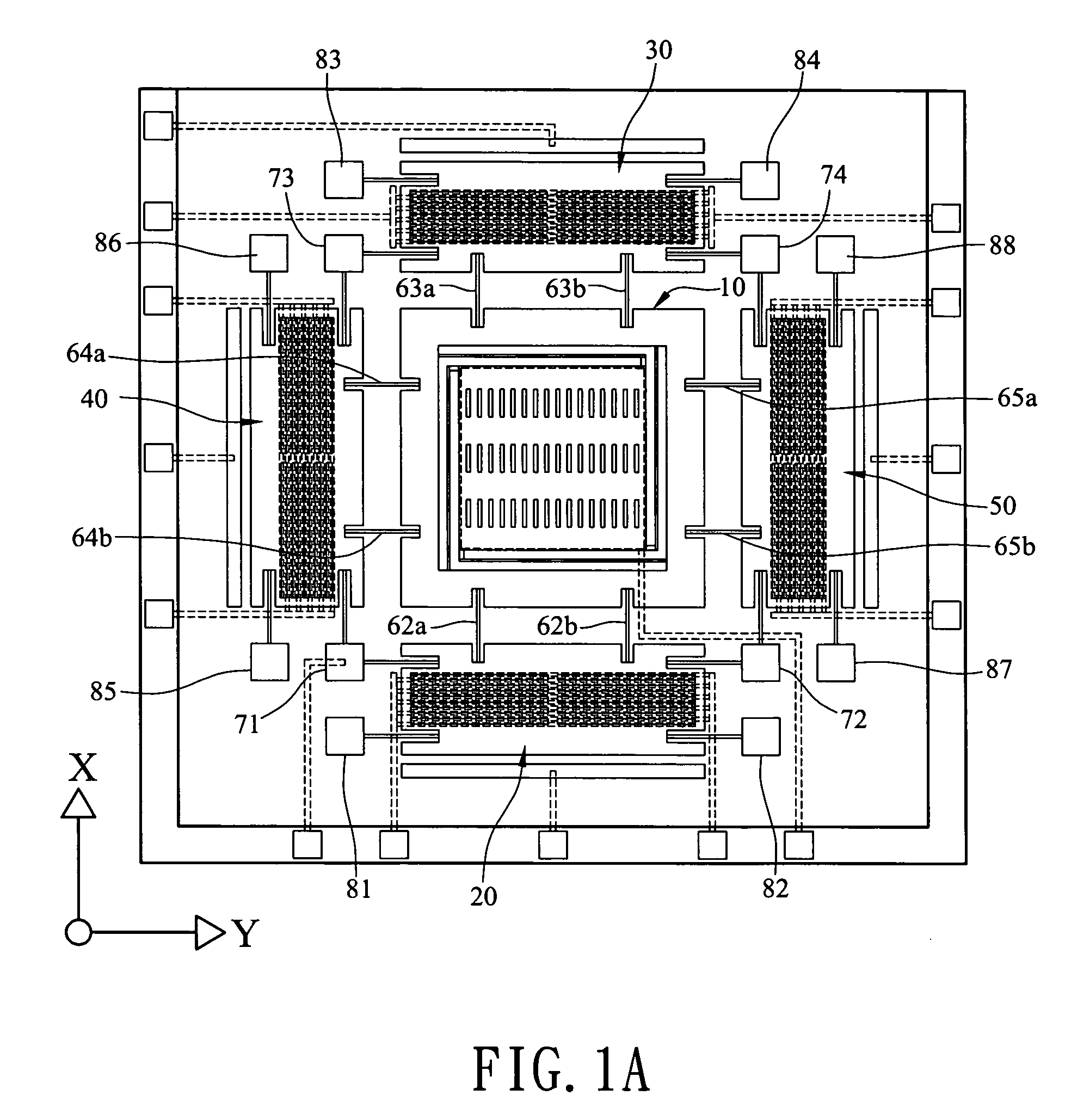
[0034]In the first embodiment, the micro accelerometer is composed of a first proof mass 10, a second proof mass 20, a third proof mass 30, a fourth proof mass 40, and a fifth proof mass 50. The proof masses are manufactured by conductive material. The second proof mass 20 and the third proof mass 30 are arranged at one of the two opposite sides of the first proof mass 10, while the third proof mass 40 and the fifth proof mass 50 are arranged at the other one of the two opposite sides of the first proof mass 10. The proof mass 20, 30, 40, and 50 are connected to the first proof mass 10 through a plurality pairs of flexible supporters 62a, 62b, 63a, 63b, 64a, 64b 65a, and 65b respectively.

[0035]The plurality of flexible supporters 62a, 62b, 63a, 63b, 64a, 64b 65a, and 65b enable the proof masses to move along a first axis (e.g., the x axis), a second axis (e.g., the y axis) parallel to the surface of the first proof mass 10, and / or a third axis (e.g., the z axis) vertical to the surf...

second embodiment

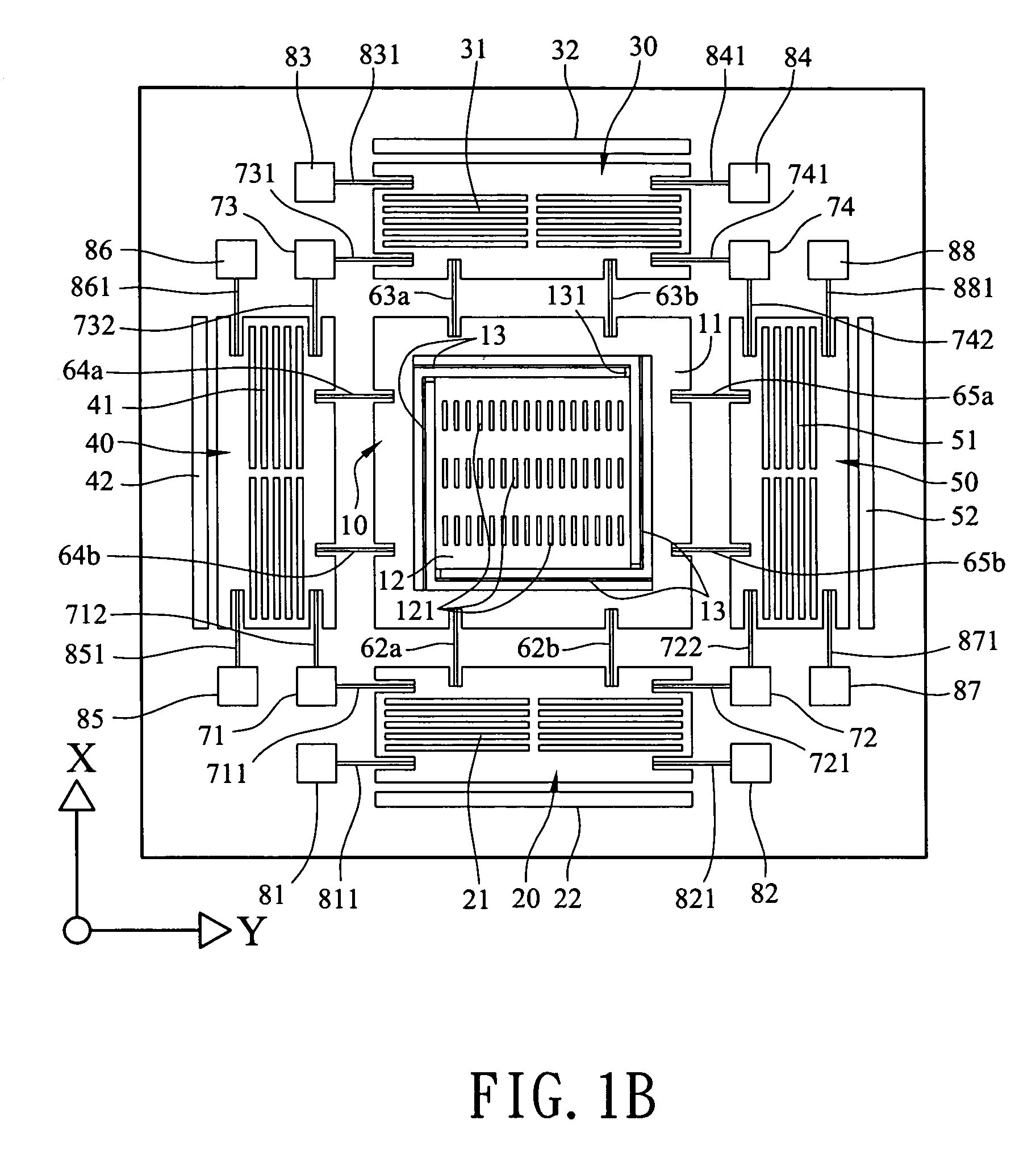
[0048]According to the principle of the invention, in the second embodiment, the close loop control electrode of the second proof mass 20 is an electrode plate 25 arranged at the exterior of the frame 11 and between the flexible supporters 62a and 62b. Thus, the proof mass 20 may return to the original position when displacement occurs owing to acceleration. Similarly, the close loop control electrode of the third proof mass 30 is an electrode plate 35 arranged at the exterior of the frame 11 and between the flexible supporters 63a and 63b. The close loop control electrode of the fourth proof mass 40 is an electrode plate 45 arranged at the exterior of the frame 11 and between the flexible supporters 64a and 64b. The close loop control electrode of the third proof mass 50 is an electrode plate 55 arranged at the exterior of the frame 11 and between the flexible supporters 65a and 65b. Thus, the proof masses 30, 40, and 50 may return to their original positions when displacement occu...

third embodiment

[0050]According to the principle of the invention, in the third embodiment, the close loop control electrode of the second proof mass 20 includes a first comb-like electrode 26 and a second comb-like electrode 27. The first comb-like electrode 26 is connected to the second proof mass 20. The comb fingers of the first comb-like electrode 26 and the second comb-like electrode 27 are arranged to interleave with each other. Thus, the proof mass 20 may return to its original position when displacement occurs owing to acceleration. The close loop control electrode of the third proof mass 30 includes a first comb-like electrode 36 and a second comb-like electrode 37. The close loop control electrode of the fourth proof mass 40 includes a first comb-like electrode 46 and a second comb-like electrode 47, while the close loop control electrode of the fifth proof mass 50 includes a first comb-like electrode 56 and a second comb-like electrode 57. The structures and functions of the comb-like e...


PUM


Abstract

A micro accelerometer including a plurality of proof masses is provided to detect the acceleration of the first axis, the second axis and the third axis. The disclosed micro accelerometer has the advantages of close loop control, mechanical decoupling, and not relying on high aspect ratio manufacturing technology.

Description

[0001]This Non-provisional application claims priority under 35 U.S.C. § 119(a) on Patent Application No(s). 093116696 filed in Taiwan, R.O.C. on Jun. 10, 2004, the entire contents of which are hereby incorporated by reference.BACKGROUND OF THE INVENTION[0002]1. Field of Invention[0003]The invention relates to an accelerometer, and, in particular, to an accelerometer that is manufactured by Micro Electro Mechanical System (MEMS) technology and has the capability of sensing one axis, two axes or three axes acceleration.[0004]2. Related Art[0005]U.S. Pat. No. 6,201,284 discloses an accelerometer which adopts proof masses to detect the acceleration of X, Y and Z axes. The proof mass detecting Z axis acceleration only moves along the Z axis, however, the motion of the proof mass detecting X axis may be coupled from the X and Y axes, and the motion of the proof mass detecting Y axis may be coupled from the X, Y and Z axes. The mechanical coupling in this structure is such that the sensin...

Claims


Application Information

Patent Timeline
Patent Type & Authority Patents(United States)
IPC IPC(8): G01P15/125G01P15/00G01P15/18
CPCG01P15/18G01P15/125G01P2015/082
Inventor LO, YUANHO, KYE-CHYNLIN, LUNG-YUNGTSAI, DENG-HORNGSCHE, SCHIU
Owner NAT CHUNG SHAN INST SCI & TECH
Why Eureka
Try Eureka