Apparatus and method for performing non-linear friction stir welds on either planar or non-planar surfaces

a friction stir and apparatus technology, applied in the direction of soldering apparatus, manufacturing tools,auxillary welding devices, etc., can solve the problems of weld defects, conventional welding processes create considerable distortion, etc., and achieve the effect of easy maneuvering work pieces

Inactive Publication Date: 2007-05-01
BRIGHAM YOUNG UNIV
View PDF13 Cites 24 Cited by
  • Summary
  • Abstract
  • Description
  • Claims
  • Application Information

AI Technical Summary

Benefits of technology

[0017]It has been disclosed previously that embodiments of this invention enable an operator to manually guide work pieces through the device. In addition, alternate novel embodiments of the invention enable the replacement of a human operator with automation, such as automatic seam tracking. Automatic seam tracking refers to the use of some form of machine vision such as a digital camera, laser scanner, or other type of sensor, to guide a mechanism along a defined path. In an automatic seam tracking embodiment of the present invention, pairs of driven rollers placed on top and below the work pieces pinch the work pieces to drive them differentially, steering the joint line along the tool by computer control. All control functions rely on sensors and computer-controlled actuators. The need for a human operator, beyond the setting up and start functions, is thus totally eliminated.
[0018]Accordingly, it is an object of some embodiments of the present invention to provide a device and system that enables non-linear welds to be made along non-linear joint lines on either planar or non-planar surfaces.
[0019]An additional object of some embodiments of the present invention is to provide a method and device for friction-stir welding that allows for welds to be made along curved and non-straight edges.
[0020]Another object of some embodiments of the present invention is to provide a method and a device for friction-stir welding that allows a user to easily maneuver work pieces through the device and along the tool.

Problems solved by technology

Conventional welding processes create considerable distortion and weld defects.

Method used


Image

  • Apparatus and method for performing non-linear friction stir welds on either planar or non-planar surfaces
  • Apparatus and method for performing non-linear friction stir welds on either planar or non-planar surfaces
  • Apparatus and method for performing non-linear friction stir welds on either planar or non-planar surfaces

Examples


Embodiment Construction

[0032]It is emphasized that the present invention, as illustrated in the figures and description herein, can be embodied in other forms. Thus, neither the drawings nor the following more detailed description of the various embodiments of the system and method of the present invention limit the scope of the invention. The drawings and detailed description are merely representative of the particular embodiments of the invention; the substantive scope of the present invention is limited only by the appended claims. The various embodiments of the invention will best be understood by reference to the drawings, wherein like elements are designated by like alphanumeric characters throughout.

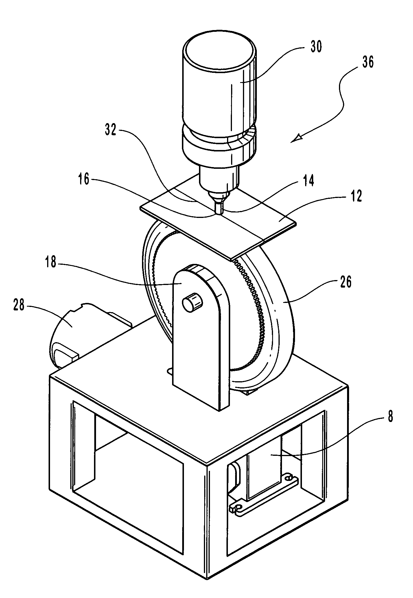
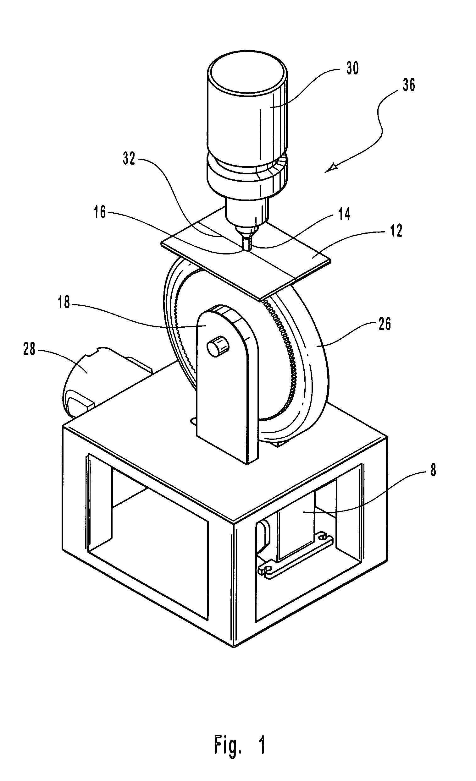
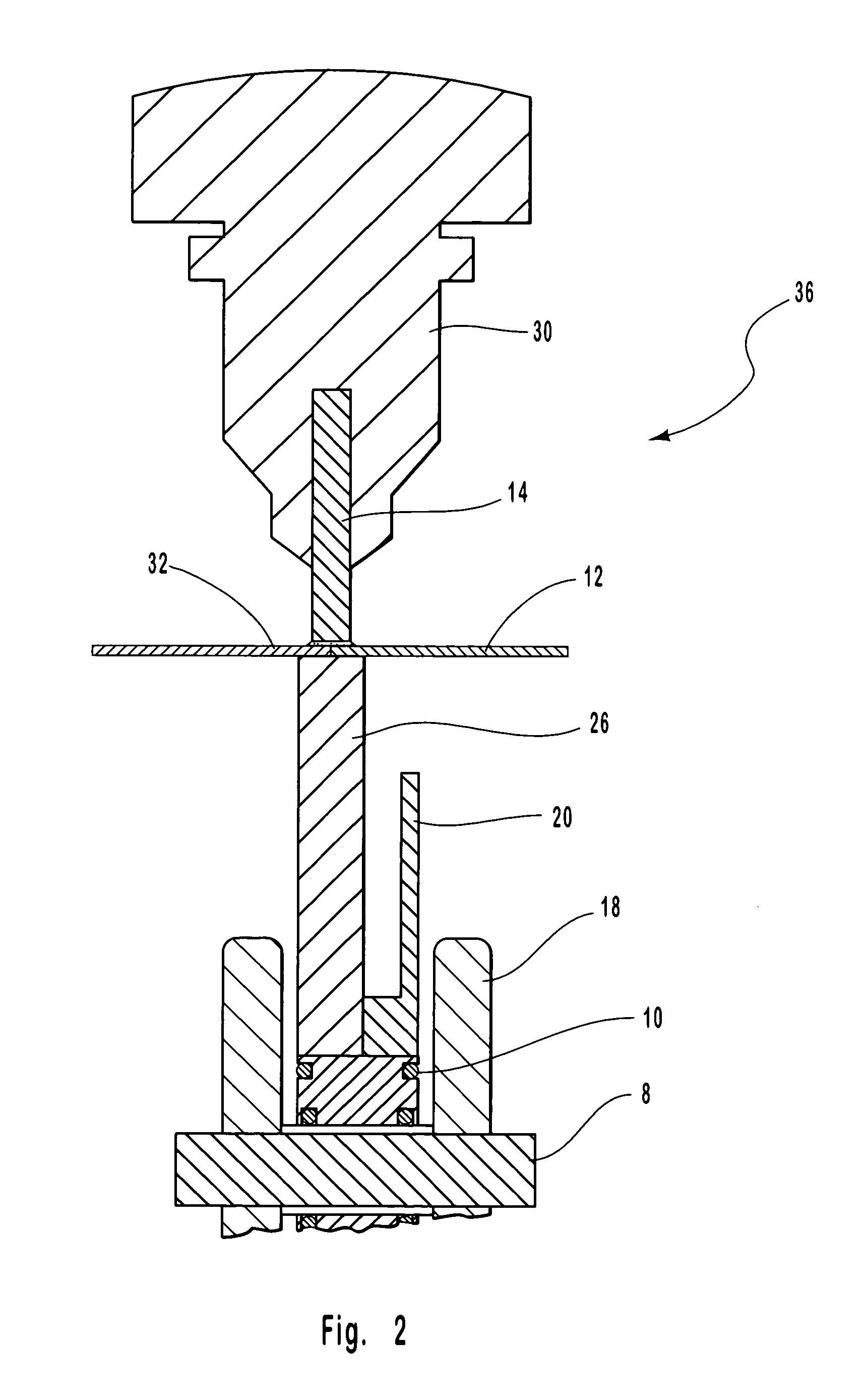
[0033]With reference now to the accompanying drawings, FIGS. 1 and 2 depict one embodiment of the friction-stir welding device 36 and method described herein with work pieces 12. In this figure, the non-consumable tool 14, with its profiled, probed end 16, is shown engaged in the joint line 32 between t...


PUM

PropertyMeasurementUnit
melting temperatureaaaaaaaaaa
diameteraaaaaaaaaa
dimensionaaaaaaaaaa

Abstract

A method and device enabling friction stir welding along non-linear joint lines or seams on either planar or non-planar surfaces are provided. The device features four roller clamps located on upper and lower pieces. It also contains a non-consumable tool with a profiled probed end that engages work pieces and follows along a non-linear or linear joint lines in order to achieve high-integrity friction stir welds. No special anvil is required and the device can be manually or automatically operated and controlled. Operating similarly to a conventional sewing machine, this device and process enable an operator or user to manually guide work pieces to be welded through a friction stir welding tool and allows for flexibility in the path of the weld and the types of material being welded.

Description

RELATED APPLICATION [0001]This application claims priority to U.S. Provisional Patent Application Ser. No. 60 / 295,663, filed on Jun. 4, 2001, and entitled “APPARATUS AND METHOD FOR PERFORMING NON-LINEAR FRICTION STIR WELDS ON EITHER PLANAR OR NON-PLANAR SURFACES.”BACKGROUND [0002]1. Field of Invention[0003]This invention relates to an apparatus and method for friction-stir welding, and more particularly, to an apparatus and method for friction-stir welding along non-linear joints on either planar or non-planar surfaces.[0004]2. Background of the Invention[0005]A recent development in the welding industry, known as friction-stir welding, has revolutionized welding techniques and devices worldwide. Friction-stir welding involves plunging a non-consumable tool with a profiled, probed end into a joint line between two pieces of metal. A joint line is the small gap formed between pieces of metal being held tightly together. This gap is where the friction-stir weld occurs.[0006]Specifical...

Claims


Application Information

Patent Timeline
Patent Type & Authority Patents(United States)
IPC IPC(8): B23K20/12
CPCB23K20/126
Inventor NELSON, TRACY W.SORENSEN, CARL D.CARTER, PERRY W.KIRKHAM, JR., THOMAS L.KIRKHAM, DAVID V.
Owner BRIGHAM YOUNG UNIV
Why Eureka
Try Eureka