Method for relieving spring seat mounting stresses

a technology of mounting stress and spring seat, which is applied in the direction of spring/damper, resilient suspension, vehicle components, etc., can solve the problems of substantial increase in spring fatigue life, and achieve the effect of reducing the stress on the middle section of the leaf spring, increasing spring fatigue life, and doubling spring fatigue li

Inactive Publication Date: 2007-05-01
ARVINMERITOR TECH
View PDF18 Cites 7 Cited by
  • Summary
  • Abstract
  • Description
  • Claims
  • Application Information

AI Technical Summary

Benefits of technology

[0006]A leaf spring assembly designed according to the invention includes a shallow cutout disposed within a spring seat section. The cutout is positioned within the clamped section of the spring seat section that supports a leaf spring. The cutout supports the leaf spring at the edges in order to relieve constraints on the leaf spring middle section. Relief of the middle section of the leaf spring distributes stresses uniformly across the leaf spring. The uniform distribution of stresses within the leaf spring results in an increase in spring fatigue life. As appreciated, every 10% reduction in spring stress results in a doubling of spring fatigue life. The cutout within the spring seat provides a uniform distribution across the entire leaf spring. The uniform distribution results in a substantial increase in spring fatigue life.
[0007]Accordingly, a leaf spring assembly designed according to this invention provides a uniform stress distribution across the leaf spring to substantial increase in spring fatigue life.

Problems solved by technology

The uniform distribution of stresses within the leaf spring results in an increase in spring fatigue life.
The uniform distribution results in a substantial increase in spring fatigue life.

Method used


Image

  • Method for relieving spring seat mounting stresses
  • Method for relieving spring seat mounting stresses
  • Method for relieving spring seat mounting stresses

Examples


Embodiment Construction

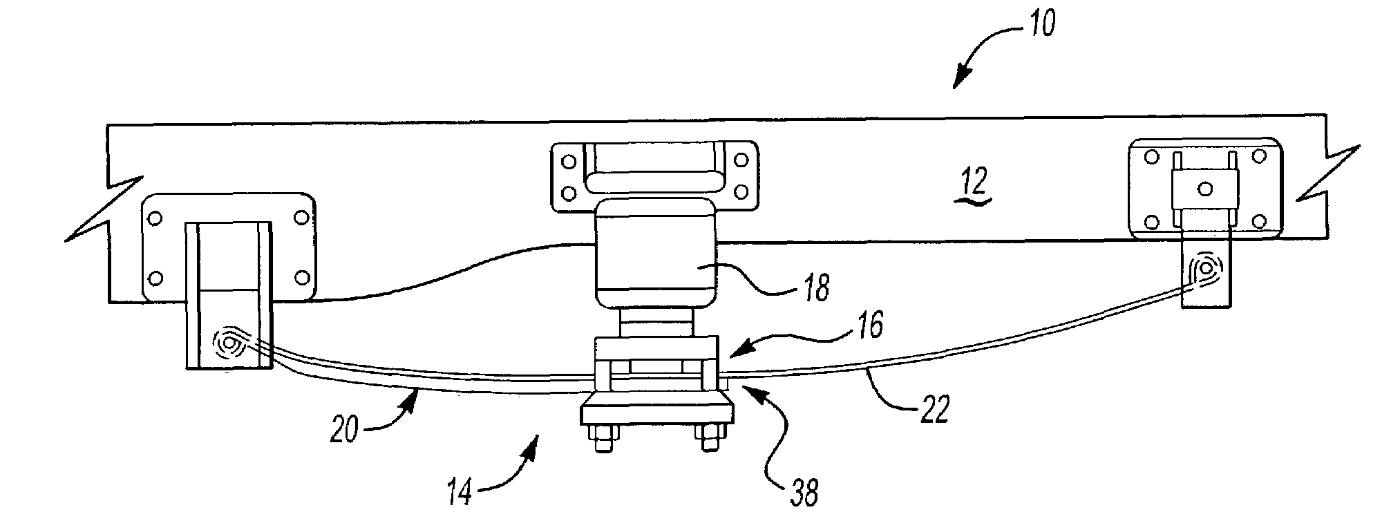
[0017]Referring to FIG. 1, a suspension assembly 10 includes a spring scat 20 and a full leaf spring 22. The suspension assembly 10 is attached to a portion of the vehicle frame 12. The suspension assembly 10 includes a leaf spring assembly 14. A clamp 16 secures the spring seat 20 to the leaf spring 22 at a central section. The clamp 16 is also a mounting point for a suspension member 18. The spring seat 20 supports a portion of the leaf spring 22 from a mounting point to the clamp 16. in this illustrated example, the suspension member 18 is an air spring. The specific configuration of the spring suspension assembly at 10 is as known in the art and is only one illustration of a suspension assembly that can benefit from the descriptions of this invention.

[0018]The leaf spring 22 extends between support structures affixed to the frame 12. Spring seat 20 is clamped at a central section 38 to the leaf spring 22. It is at this portion in the center section 38 where the highest amount of...


PUM


Abstract

A spring assembly includes a spring seat clamped to a leaf spring at a center portion. The spring seat includes a cutout for distributing clamping stresses in a substantially uniform manner across the leaf spring. The cutout provides a relief for a central portion of the leaf spring to uniformly distribute clamping pressures across the leaf spring. Uniformly distributing stresses across the width of the spring increases leaf spring fatigue life.

Description

BACKGROUND OF THE INVENTION[0001]This invention generally relates to a leaf spring assembly and specifically to a method of relieving leaf spring mounting stresses.[0002]Conventional leaf springs for vehicle suspensions comprise flat rolled steel strips having a substantially rectangular cross-sectional shape along a plane perpendicular to the longitudinal direction of each steel strip. The leaf spring assembly includes a clamped center portion for mounting of an axle and a suspension member. The suspension member is typically a coil or air spring to further absorb road inconsistencies. The highest stresses on the leaf spring are experienced in the clamped section of the leaf spring. Many stress relieving techniques and methods have been used in conventional leaf spring assemblies in order to reduce negative affects that high stress concentrations produce.[0003]One conventional leaf spring assembly includes a short spring seat member and a single long leaf spring member. The long le...

Claims


Application Information

Patent Timeline
Patent Type & Authority Patents(United States)
IPC IPC(8): B60G11/02B60G11/46F16F1/26
CPCB60G11/465F16F1/26
Inventor PLATNER, DAVID K.SOMNAY, RAJESH J.WEN, XINYU
Owner ARVINMERITOR TECH
Why Eureka
Try Eureka