Optical connector with memory function

a technology of optical connectors and memory functions, applied in the field of optical connectors, can solve the problems of inconvenience in handling connectors, affecting the convenience of operation using control information of this type, and erroneous understanding or erroneous input of control information, etc., and achieve the effect of convenient handling of connectors

Inactive Publication Date: 2007-05-01
TOKYO TSUSHINKI INDS
View PDF3 Cites 142 Cited by
  • Summary
  • Abstract
  • Description
  • Claims
  • Application Information

AI Technical Summary

Problems solved by technology

In this case, mistake such as erroneous understanding or erroneous inputting of control information shall be occasionally occurred, if letters are employed as the control information, since an operator performs the inputting operations in reading of the letters of control information.
Accordingly, if the read-in operation is overlooked at a working operation step, reliable control of this working operation step cannot be performed.
In this case where optical connectors carrying control information of these label and tape are accumulated on a distributing board in a real application circumstance, the label itself becomes considerable obstacle for freely manipulation so that the convenience of operation using the control information of this type is disturbed.
Furthermore, if material of the label and the tape is of paper, the label and the tape may be damaged, so that the control information cannot be recognized and then controlled.

Method used


Image

  • Optical connector with memory function
  • Optical connector with memory function
  • Optical connector with memory function

Examples


Embodiment Construction

[0019]The present invention will be more precisely described with reference to accompanying drawings.

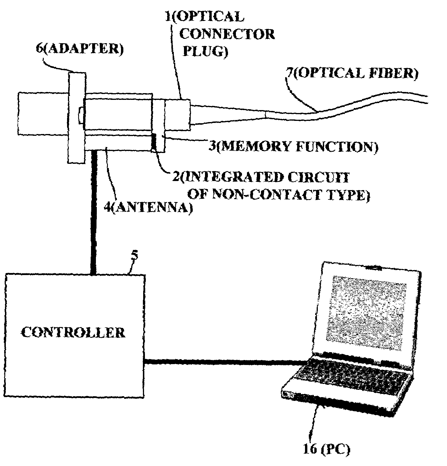
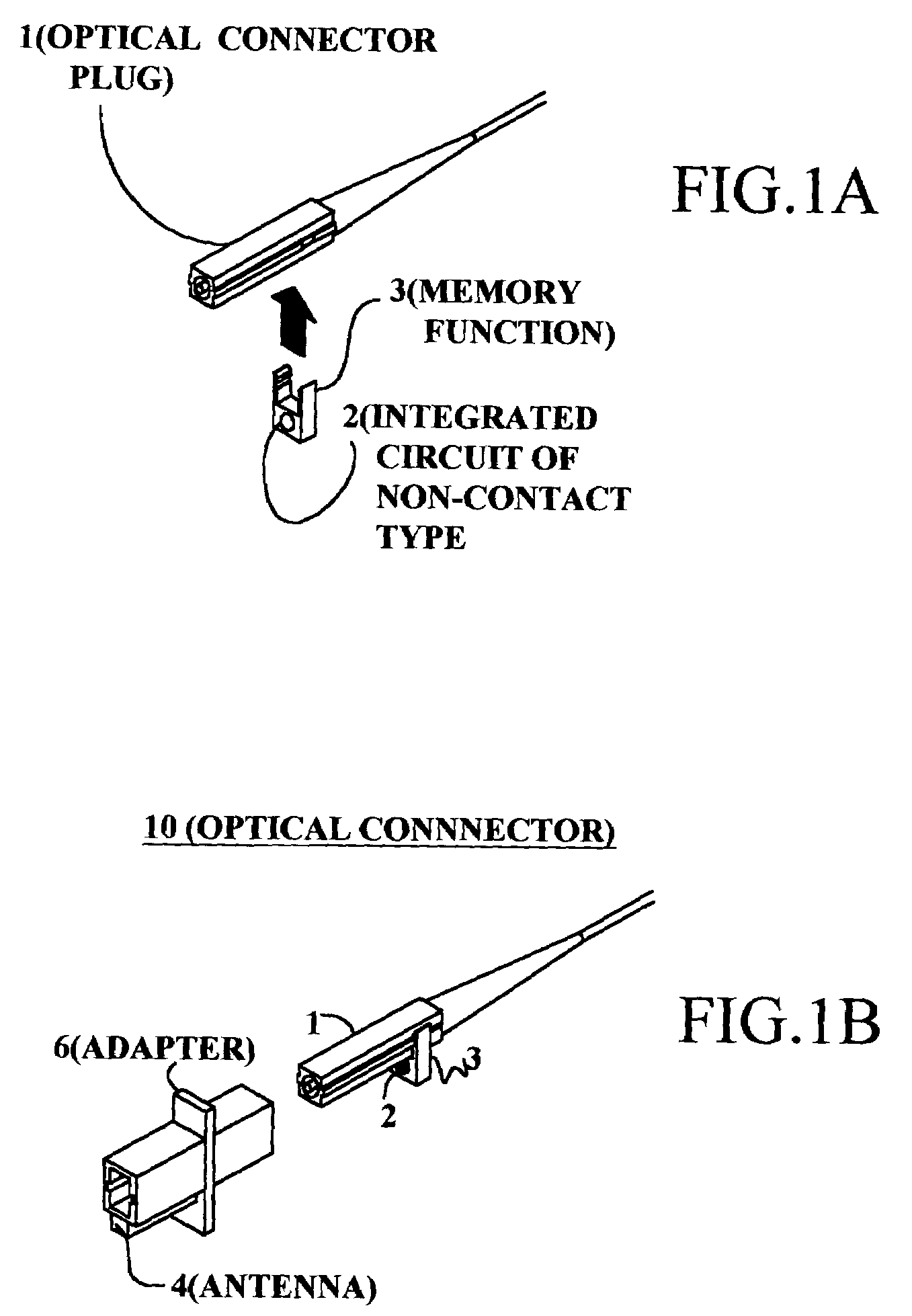
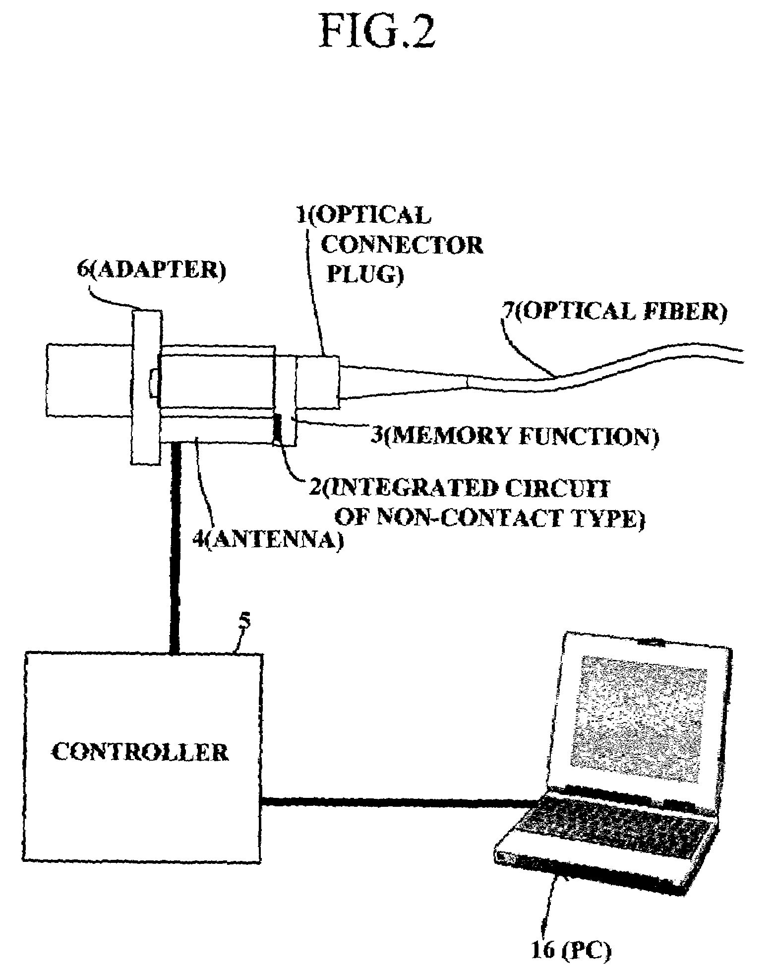
[0020]An optical connector 10 with memory function of the present invention comprises, as illustrated in FIG. 1A and FIG. 1B, an optical connector plug 1 including an optical connection portion, and a memory function 3 having an integrated circuit of non-contact type, which is formed into an electromagnetic induction system applied to IC cards and IC fixed-term tickets developed as RFID (Radio Frequency Information Distributor) systems. Moreover, a read-write device comprises, as shown in FIG. 2, an antenna 4 having electromagnetic induction coupling to the integrated circuit 2 of non-contact type, and a controller 5 provided for controlling the antenna 4.

[0021]When the optical connector plug 1 is inserted into an adapter 6 as shown in FIG. 2, the controller 5 communicates to the memory function 3 of the side of the optical connector 10 by way of the antenna 4 positioned near the ada...


PUM


Abstract

An optical connector with memory function comprises memory function for storing respective identification information in order to readily and exactly perform separate control of respective control steps and further to obtain convenient handling of connectors. The optical connector with memory function 3 of the present invention is characterized by a memory function capable of untouchably performing, from outside thereof, writing-in and reading-out of necessary information. The memory function has a structure mounted on or mountable on the outer construction of a housing accommodating therein the optical connection portion of an optical connector plug in the optical connector with memory function.

Description

[0001]This application claims priority from International Application No. PCT / JP03 / 00082, filed Jan. 8, 2003, which in turn claims priority from Japanese Application No. 005642 / 2002, filed Jan. 15, 2002.TECHNICAL FIELD[0002]The present invention relates to an optical connector, and, especially, to an optical connector with memory function for control information.BACKGROUND OF THE INVENTION[0003]On many conventional optical connectors, a label or a tape, on which optional letters or bar codes are recorded, is pasted for individual control information. In other examples, grouped control information, such as lot numbers or manufactured dates, is recorded.[0004]In case of controlling production steps or mounting and wiring steps of optical connectors in these conditions, such control operations are usually performed by the use of computers. In this case, mistake such as erroneous understanding or erroneous inputting of control information shall be occasionally occurred, if letters are e...

Claims


Application Information

Patent Timeline
Patent Type & Authority Patents(United States)
IPC IPC(8): G02B6/36G02B6/38
CPCG02B6/3807G02B6/3895G02B6/3897G06K19/07758
Inventor SAGO, MASUYUKIENOMOTO, MASANORI
Owner TOKYO TSUSHINKI INDS
Why Eureka
Try Eureka