
Magnetically navigable telescoping catheter and method of navigating telescoping catheter

a telescoping catheter and navigable technology, applied in the field of magicically navigable telescoping catheters, can solve the problems of limited number of directions of movement, procedure can be extremely tedious and time-consuming, and previously available navigable devices and navigation methods are only marginally acceptable for some procedures, so as to improve accuracy, reduce procedure times, and superior control of the distal end of the catheter

Inactive Publication Date: 2007-05-01
STEREOTAXIS
View PDF29 Cites 255 Cited by
  • Summary
  • Abstract
  • Description
  • Claims
  • Application Information

AI Technical Summary

Benefits of technology

"The present invention is a magnetically navigable telescoping catheter that allows for better control and positioning of its distal end in the body. The catheter has a sleeve and an extension member that can be telescoped in and out of the sleeve, with the distal end of the extension member being more flexible than the sleeve. The catheter can be used for various procedures such as cardiac mapping, pacing, or ablation. The method of navigating the catheter involves applying a magnetic field to orient the distal end of the extension member and controlling the position of the catheter by either telescoping the extension member or the sleeve. The telescoping motion and magnetic guidance of the catheter allows for better control and accuracy, reducing procedure times and allowing for successful completion of the procedures."

Problems solved by technology

However, previously available navigable devices and navigation methods are only marginally acceptable for some procedures where high precision is required.
Such a procedure can be extremely tedious and time consuming with previously available devices and navigation methods.
These mechanically actuable catheters typically have a limited number of directions of movement.
Moreover to navigate the distal end of the catheter to a particular point, the catheter had to be rotated, but rotation of the proximal end of the catheter did not always directly translate to rotation at the distal end, particularly where the path of the catheter was convoluted.
Moreover, twists and turns in the catheter would impair or eliminate the ability to control the distal end of the catheter.
However, not for navigation.

Method used


Image

  • Magnetically navigable telescoping catheter and method of navigating telescoping catheter
  • Magnetically navigable telescoping catheter and method of navigating telescoping catheter
  • Magnetically navigable telescoping catheter and method of navigating telescoping catheter

Examples


Embodiment Construction

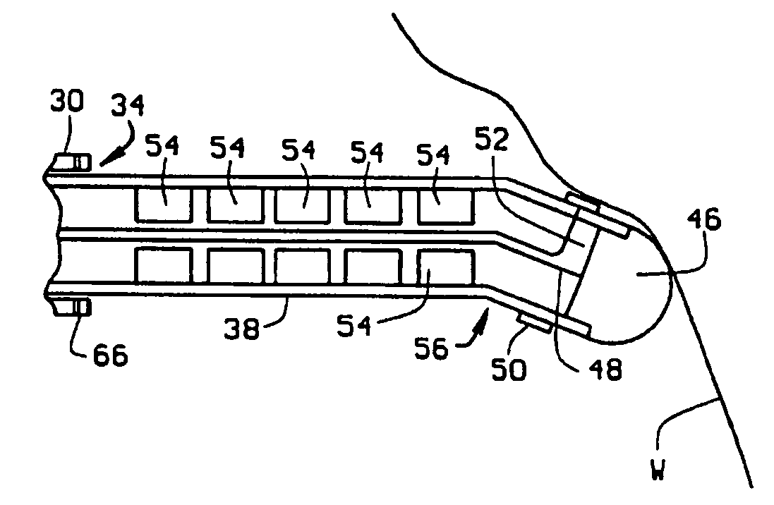
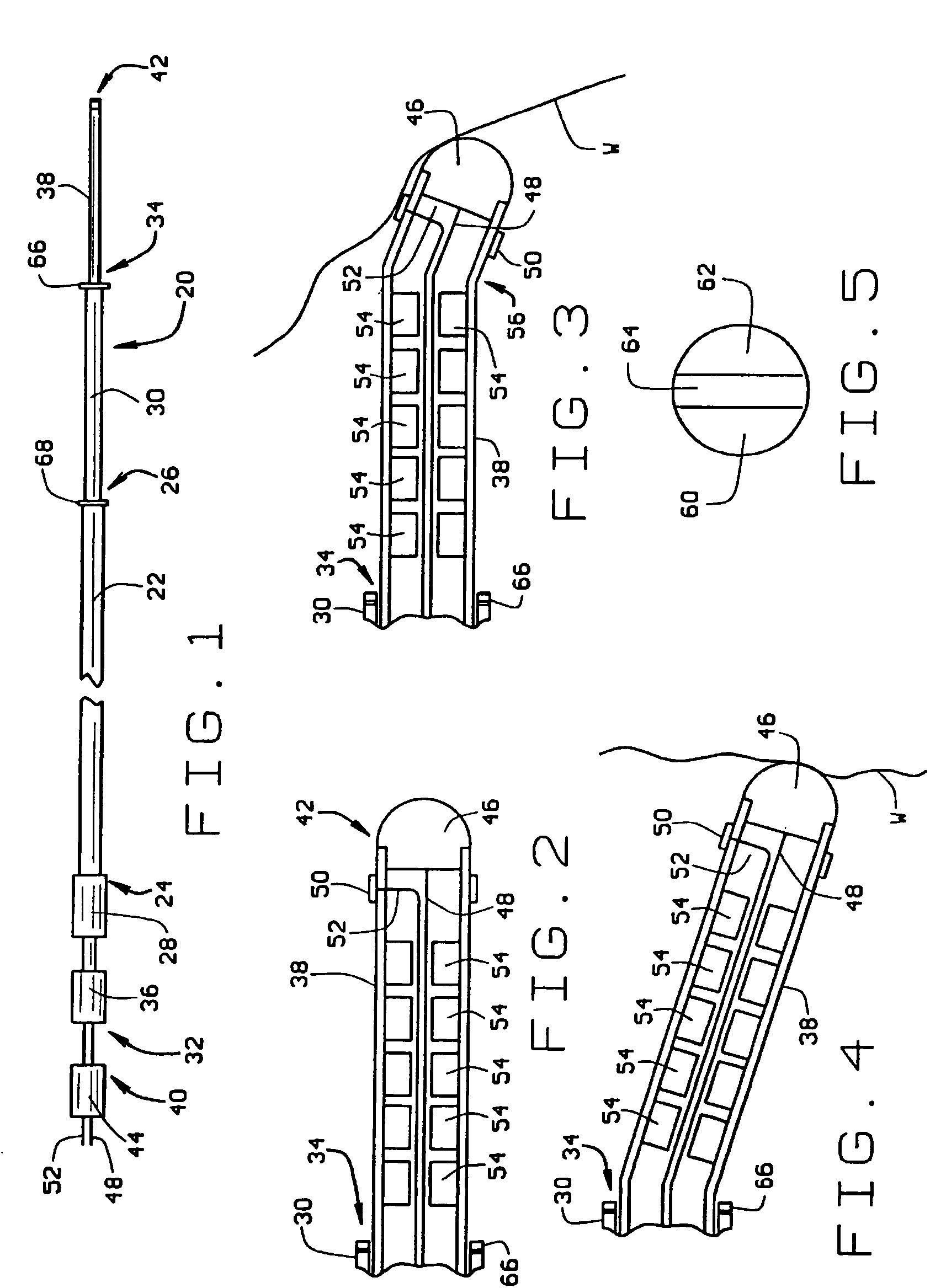
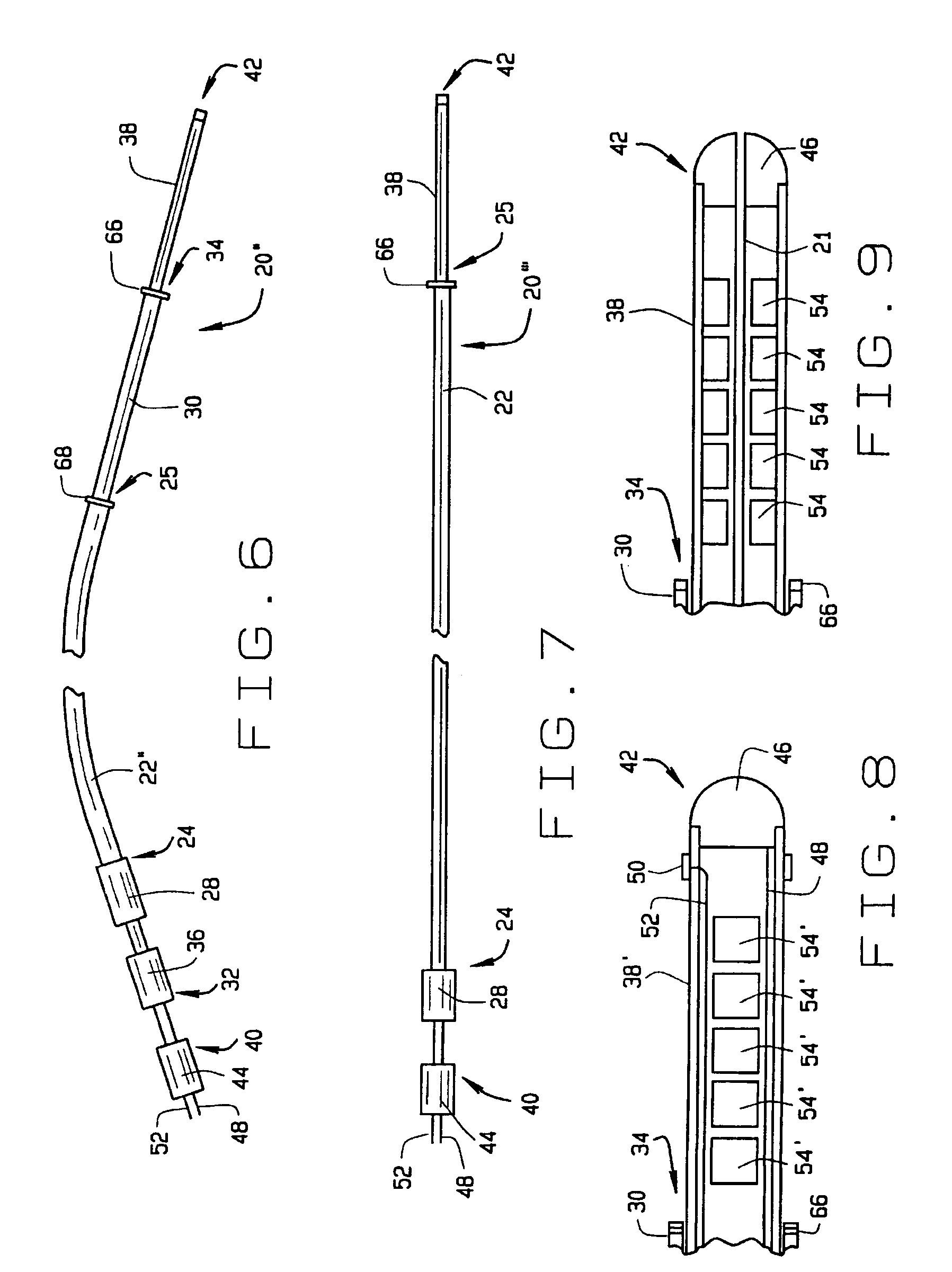
[0027]A catheter constructed according to the principles of the present invention is indicated generally as 20 in FIG. 1. As shown in the figures and described herein, catheter 20 is an electrode catheter having one or more electrodes thereon, but this invention is not so limited and the catheter can be used for other purposes, for example the delivery of diagnostic or therapeutic agents. FIG. 9 shows such a catheter 20′ with a central passage 21 for the delivery of diagnostic or therapeutic agents.

[0028]The electrode catheter 20 of the preferred embodiment comprises a sheath 22 having a proximal end 24 and a distal end 26. The sheath 22 is preferably about 120 cm long. There is a connector block 28 at the proximal end of the sheath 22. The sheath 22 is preferably made from conventional sheath material, with an outside diameter of about 9 French. As shown in FIG. 6, instead of the straight sheath 22, in an alternate construction of the electrode catheter 20″, the sheath 22″ may be p...


PUM


Abstract

A magnetically navigable catheter includes a sheath having a proximal end and a distal end, and an extension member having a proximal end and a distal end, slidably mounted in the sheath so that the distal end portion of the extension member telescopes from the distal end of the sheath. The distal end portion of the extension member being relatively more flexible than the distal end of the sheath. There may be one or more electrodes on the distal end of the extension member. There is also at least one magnet, and preferably more than one magnet, on the distal end portion of the extension member to allow the distal end of extension member to be oriented by the application of an externally applied magnetic field. The catheter preferably also includes a sleeve, having a proximal end and a distal end, the sleeve being slidably mounted in the sheath so that the distal end portion of the sleeve telescopes from the distal end of the sheath, so that the sleeve can be selectively extended and retracted relative to the sheath, and the extension member can be selectively extended and retracted relative to the sleeve. According to the method of this invention, the distal end of the electrode catheter is introduced into the part of the body where the electrode will be used to contact the specific body structures, and the electrode is moved into contact with the body structure by applying an external magnetic field and selectively telescoping the extension member relative to the sheath to bring the electrode on the distal end of the extension member into contact with the specific body structure.

Description

[0001]This application is a continuation application of U.S. patent application Ser. No. 09 / 999,185, filed Feb. 4, 2002, now abandoned, which is a continuation application of U.S. patent application Ser. No. 09 / 393,521, filed Sep. 10, 1999, now U.S. Pat. No. 6,385,472, issued May 7, 2002, (incorporated herein by reference).FIELD OF THE INVENTION[0002]This invention relates to a magnetically navigable telescoping catheter and a method of magnetically navigating a telescoping catheter within open body spaces.BACKGROUND OF THE INVENTION[0003]Many medical procedures require the ability to accurately navigate medical devices inside the body. In the past, this has been accomplished with mechanically steerable devices. More recently, magnetically navigable medical devices have been developed that can be navigated with an externally applied magnetic field.[0004]However, previously available navigable devices and navigation methods are only marginally acceptable for some procedures where hig...

Claims


Application Information

Patent Timeline
Patent Type & Authority Patents(United States)
IPC IPC(8): A61B18/18A61B5/04A61B5/042A61B5/06A61B18/14A61M25/01
CPCA61B5/0422A61B18/1492A61M25/0127A61B5/06A61B2018/00577A61B2018/00839A61B2018/1253A61B2018/126A61B2562/0209A61B2562/043A61B5/287
Inventor HALL, ANDREW F.BLUME, WALTER M.
Owner STEREOTAXIS
Learn More