
Dynamic lordotic guard with movable extensions for creating an implantation space posteriorly in the lumbar spine and method for use thereof

a technology of lordotic guards and movable extensions, which is applied in the field of dynamic lordotic guards with movable extensions for creating an implantation space posteriorly in the lumbar spine and method for using thereof, can solve the problems of difficult removal of distractor elements, and achieve the effect of convenient insertion and removal, quick spacing and positioning, and safe and effective spacing and positioning

Active Publication Date: 2007-05-01
WARSAW ORTHOPEDIC INC
View PDF22 Cites 169 Cited by
  • Summary
  • Abstract
  • Description
  • Claims
  • Application Information

AI Technical Summary

Benefits of technology

[0029]The present invention has a number of embodiments, at least some of which have as an object of at least one embodiment of the present invention to provide a device and method for quickly, safely, effectively, and accurately spacing apart and positioning a pair of adjacent vertebral bodies to receive an implant, which is anything designed to be left in the body for an extended length of time, working upon the properly positioned vertebral body end plate regions adjacent a disc space so as to remove bone to produce a receiving surface corresponding to an implant having upper and lower surfaces to be implanted between the adjacent vertebrae.
[0030]It is a further object of at least one embodiment of the present invention to provide a device and method that permits the insertion of disc penetrating extensions of a guard into the disc space posteriorly in a first position that facilitates insertion and removal of the disc penetrating extensions into and from the disc space and then permits the disc penetrating extensions to be moved into a second position that orients the adjacent vertebral bodies in a preferred lordotic relationship relative to the device and each other.

Problems solved by technology

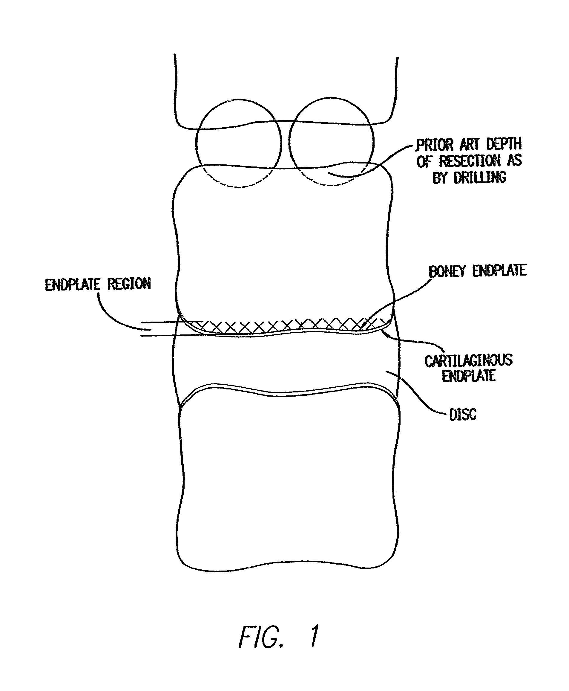
Then, after an implant is inserted, it may be difficult to remove a distractor element such as a guard having disc penetrating extensions having a maximum height greater then the height of the disc space posterior height.

Method used


Image

  • Dynamic lordotic guard with movable extensions for creating an implantation space posteriorly in the lumbar spine and method for use thereof
  • Dynamic lordotic guard with movable extensions for creating an implantation space posteriorly in the lumbar spine and method for use thereof
  • Dynamic lordotic guard with movable extensions for creating an implantation space posteriorly in the lumbar spine and method for use thereof

Examples


Embodiment Construction

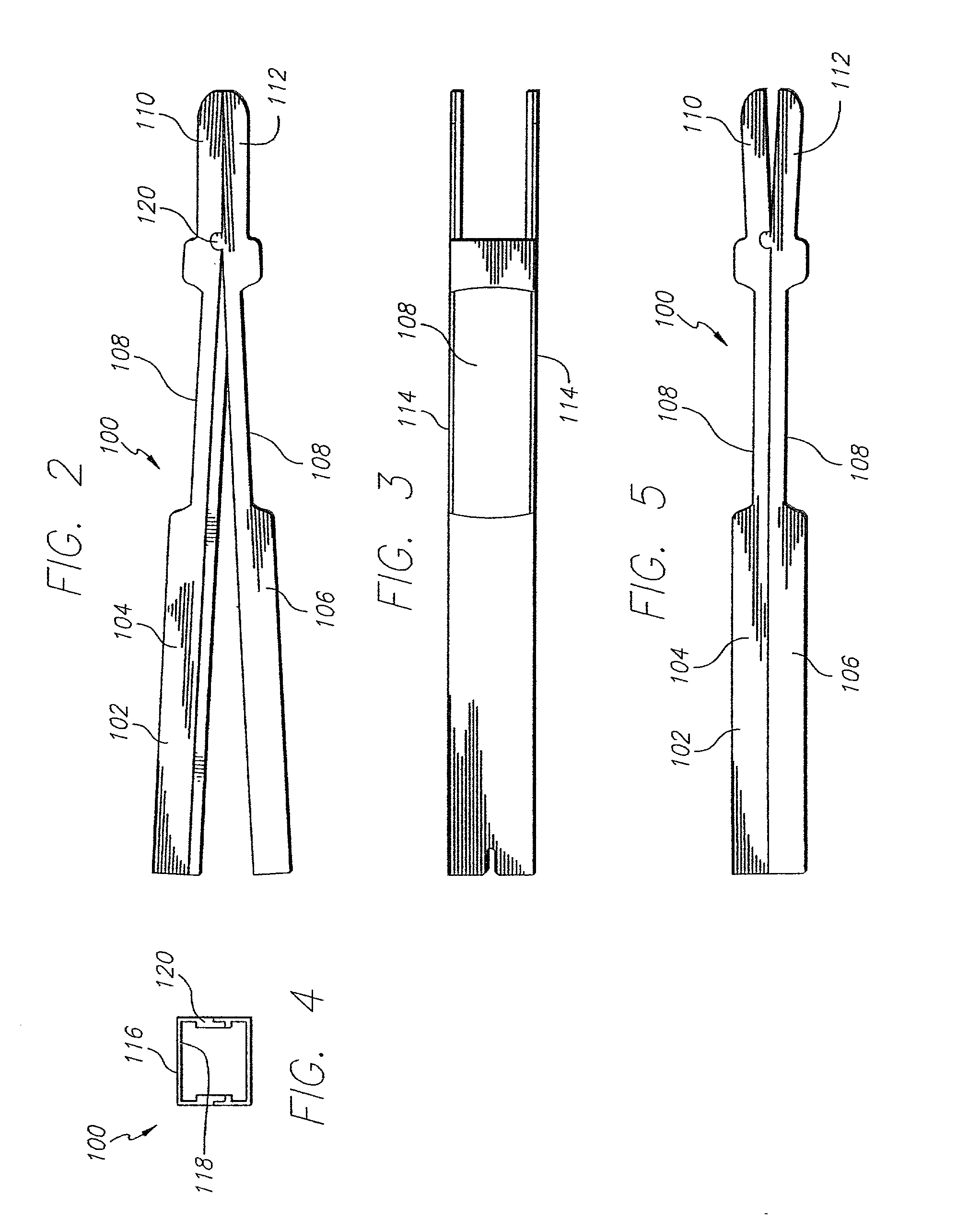
[0086]Reference is now made in detail to the present preferred embodiments of the invention, as illustrated in the accompanying drawings. Wherever possible, the same reference numbers are used throughout the drawings to refer to the same or like parts. For example, reference numbers without a prime are used in relation to a guard having a rectangular cross-section such as described with reference to FIGS. 2–27. Reference numbers with a prime are used in relation to a guard having a circular cross-section or opposed upper and lower arcuate portions such as described with reference to FIGS. 28–45.

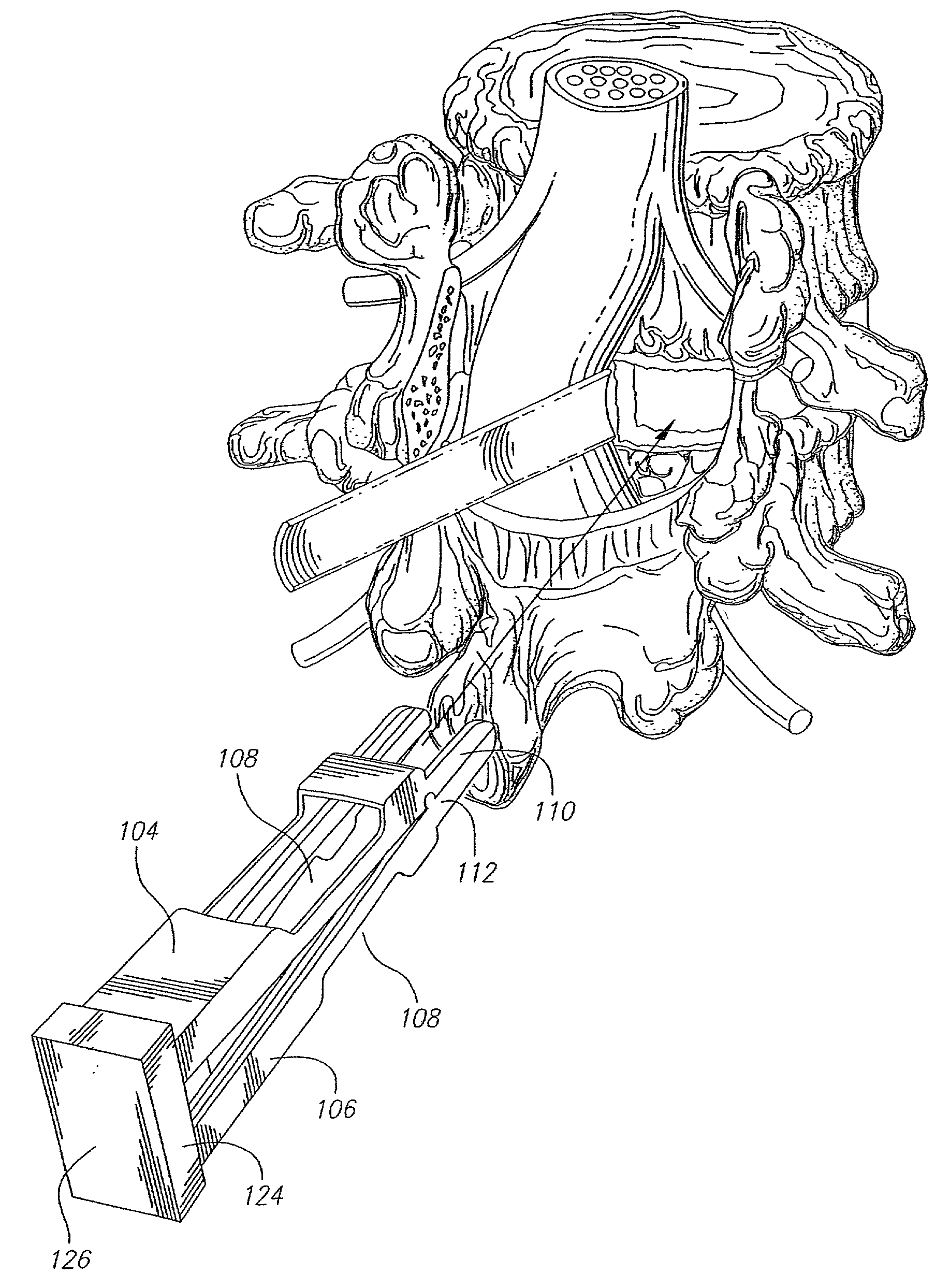
[0087]FIGS. 2–5 are generally directed to an embodiment of a guard having a rectangular cross-section for use in spinal surgery for forming an implantation space between adjacent vertebral bodies of the lumbar spine from a posterior approach. As shown in FIG. 2, a guard 100 has a body 102 with a first portion 104 and a second portion 106. Guard 100 also has disc penetrating extensions 110, 11...


PUM


Abstract

A lordotic guard and method for guiding a bone removal device to form an implantation space in the human spine and, if desired, for inserting a spinal implant into the implantation space. The guard has a body having a first portion and a second portion in pivotal relationship to one another proximate the leading end between an open position and a closed position. The first and second portions define an opening for providing a protected pathway to the disc space and the adjacent vertebral bodies. At least one disc space penetrating extension extends from the leading end of the body adapted for insertion at least in part into the disc space. First and second portions of the extension are in pivotal relationship to one another about an axis that passes through at least a portion of the pathway.

Description

RELATED APPLICATIONS[0001]This application is a national stage application claiming priority to PCT Application Serial No. PCT / US02 / 06021, filed Mar. 1, 2002, which claims the benefit of U.S. provisional application No. 60 / 272,381, filed Mar. 1, 2001 and U.S. provisional application No. 60 / 272,382, filed Mar. 1, 2001, the disclosures of which are all incorporated herein by reference.FIELD OF THE INVENTION[0002]The present invention relates to a device for implantation into a disc space between adjacent vertebral bodies in the human spine, and a device and method for working on those portions of the vertebral bodies adjacent that disc space to remove bone material and thereby access vascular bone, and preferably a device and method for protecting the neurological structures such as nerve roots and dural sac proximate the implantation site while providing protected access to form an implantation space and then access the implantation space formed between the adjacent vertebral bodies ...

Claims


Application Information

Patent Timeline
IPC IPC(8): A61B17/56A61B17/00A61B17/58A61B17/02A61B17/16A61B17/17A61B17/32A61F2/00A61F2/30A61F2/44A61F2/46A61L27/00A61L31/00
CPCA61B17/025A61F2/44A61B17/1757A61B17/32002A61F2/4611A61B17/1671A61B2017/00261A61B2017/0256A61B2017/320004A61F2/442A61F2/4455A61F2002/30187A61F2002/30224A61F2002/30624A61F2002/30729A61F2002/30785A61F2002/30787A61F2002/30975A61F2002/4475A61F2002/4622A61F2002/4627A61F2002/4628A61F2230/0034A61F2230/0069A61B17/147A61F2002/30593A61B17/56A61B2017/564A61B17/88A61B17/14A61B17/15A61B17/16A61B17/1615A61B17/17A61B17/1703A61F2/447
Inventor MICHELSON, GARY K.
Owner WARSAW ORTHOPEDIC INC
Learn More