Apparatus and methods for measuring resistance of conductive layers

a technology of conductive layers and apparatuses, applied in the field of measuring electrical resistance, can solve the problems of posing a greater challenge to such test apparatuses, and achieve the effects of small resistance, improved electrical resistance measurement accuracy, and accurate, consistent resistance measuremen

Inactive Publication Date: 2007-05-01
THE BOEING CO
View PDF14 Cites 1 Cited by
  • Summary
  • Abstract
  • Description
  • Claims
  • Application Information

AI Technical Summary

Benefits of technology

[0009]The present invention is directed to apparatus and methods for measuring the electrical resistance of electrically-conductive materials. Apparatus and methods in accordance with the present invention may advantageously provide improved accuracy of electrical resistance measurements, and may enable the accurate, consistent measurement of the resistance of certain conductive materials having relatively small resistance.

Problems solved by technology

More modem conductive coatings, however, have relatively smaller resistance per square, thereby posing a greater challenge to such test apparatus.

Method used


Image

  • Apparatus and methods for measuring resistance of conductive layers
  • Apparatus and methods for measuring resistance of conductive layers
  • Apparatus and methods for measuring resistance of conductive layers

Examples


Embodiment Construction

[0018]The present invention relates to apparatus and methods for measuring the electrical resistance of materials, and more specifically, to measuring the resistance of electrically-conductive coatings on component surfaces and the like. Many specific details of certain embodiments of the invention are set forth in the following description and in FIGS. 2–6 to provide a thorough understanding of such embodiments. One skilled in the art, however, will understand that the present invention may have additional embodiments, or that the present invention may be practiced without several of the details described in the following description.

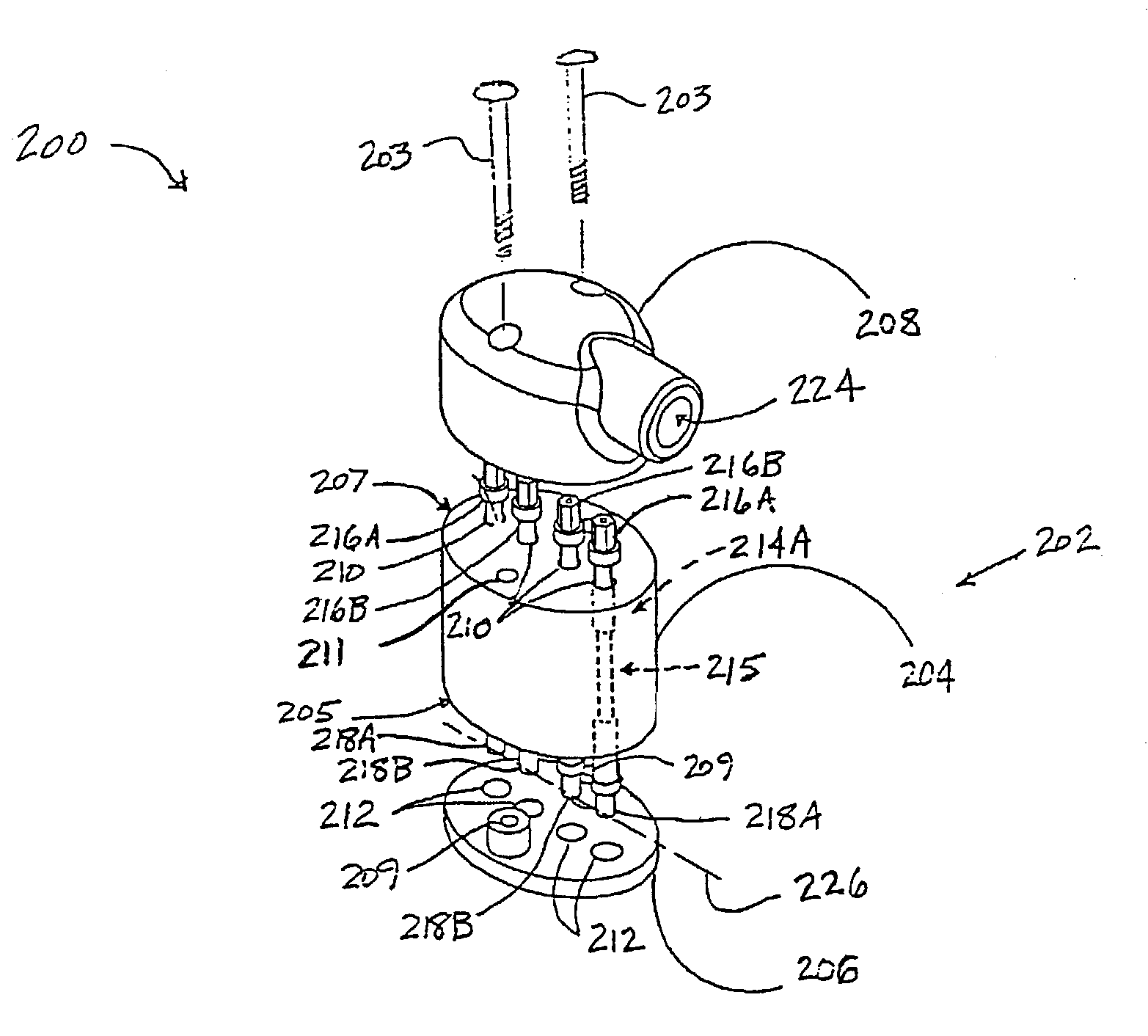
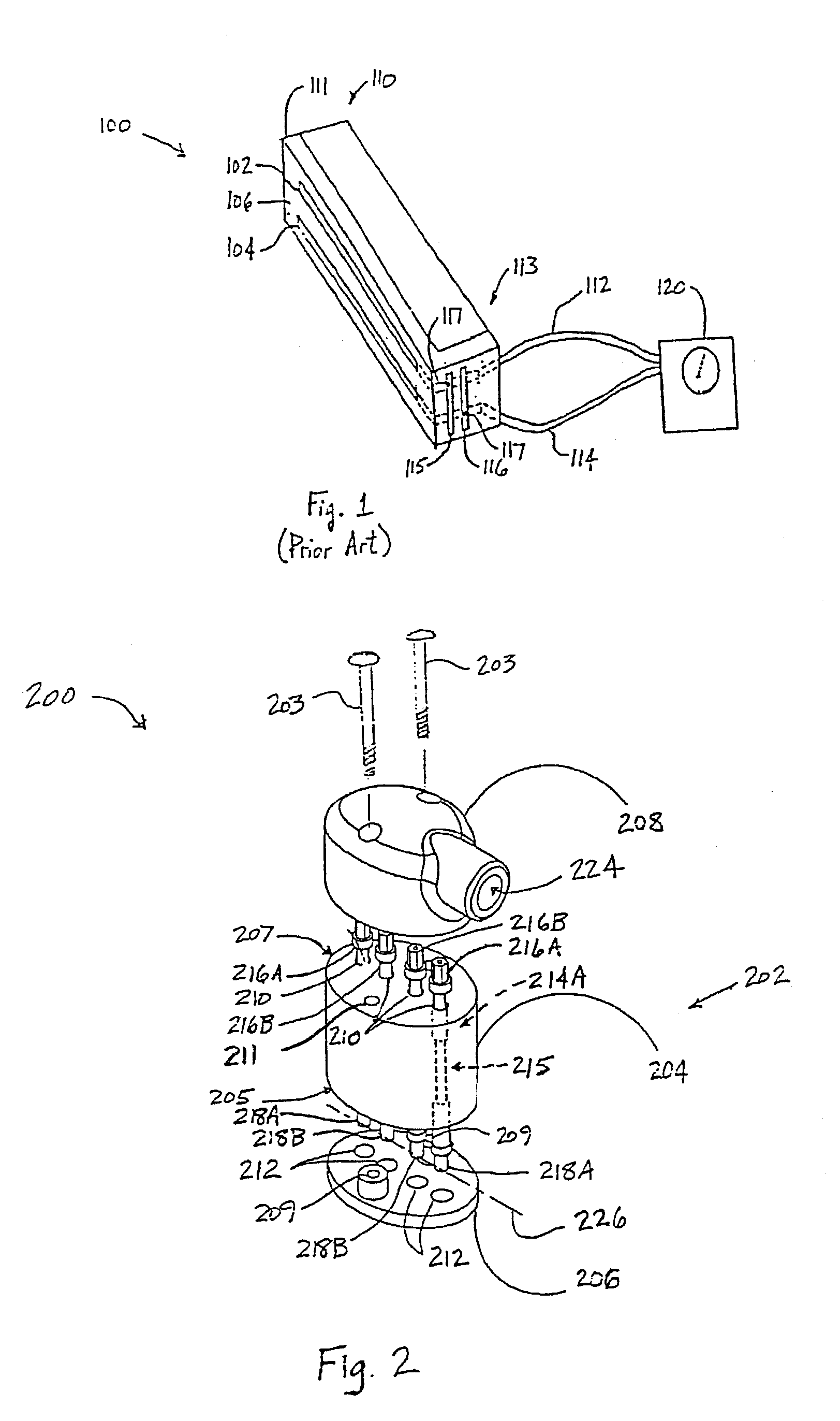
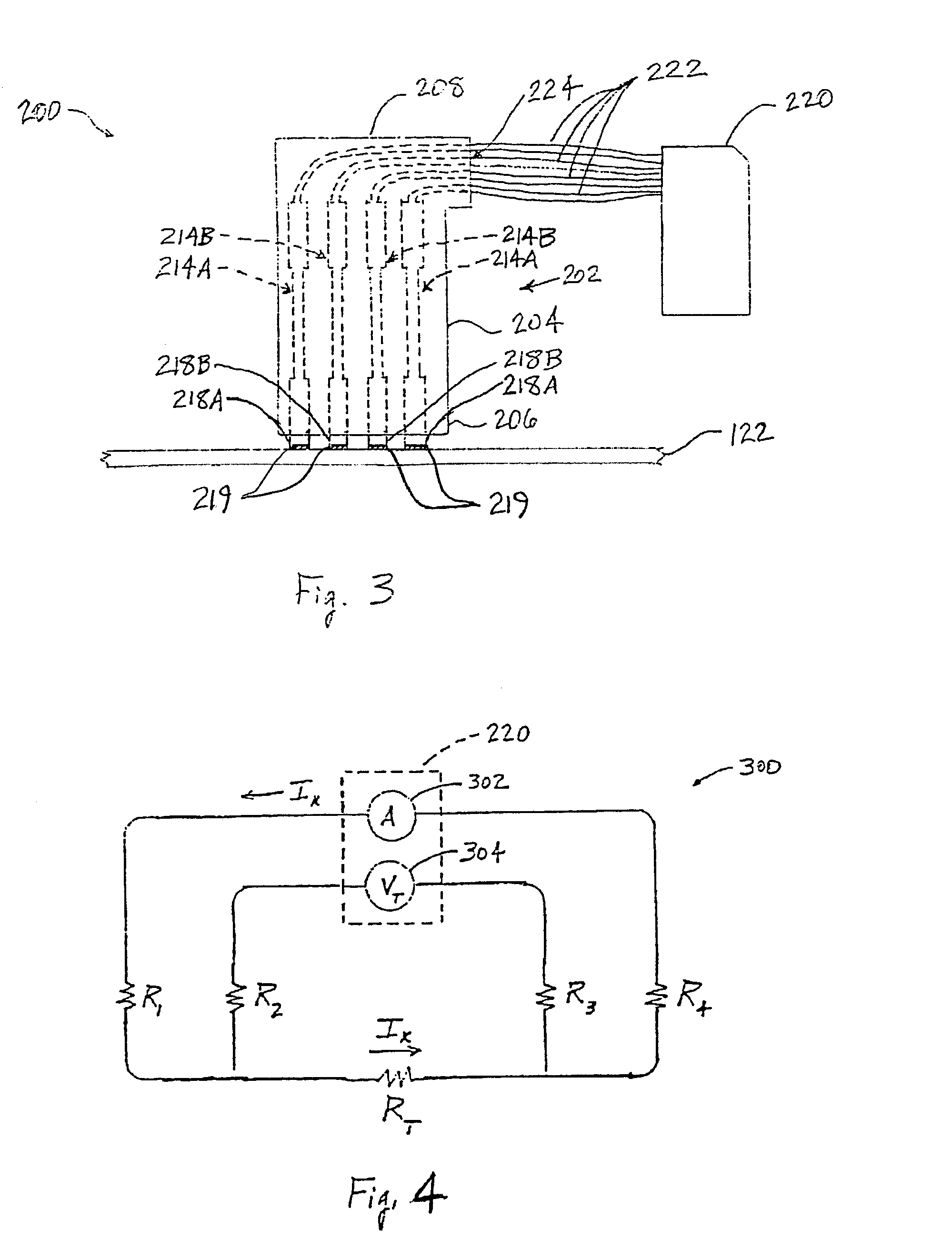
[0019]FIG. 2 is a partially-exploded isometric view of a test device 200 for measuring an electrical resistance RT of a conductive layer 122 (not shown) in accordance with an embodiment of the invention. FIG. 3 is a side elevational view of the test device 200 of FIG. 2 engaged with a conductive layer 122. In this embodiment, the test device 200 includ...


PUM


Abstract

Apparatus and methods for measuring the electrical resistance of conductive materials are disclosed. In one embodiment, an apparatus includes a housing, and first, second, third, and fourth conductive members projecting outwardly from the housing. The conductive members are engageable with an electrically-conductive material at a plurality of points distributed along a measurement axis. In an alternate embodiment, at least some of the conductive members include a spring-loaded portion such that a contact portion of the conductive member projects outwardly from the housing by a variable distance. In operation, the electrical resistance of the electrically-conductive material is determinable from a known current applied between the first and fourth conductive members, and a voltage measured between the second and third conductive members.

Description

CROSS REFERENCE TO RELATED APPLICATIONS[0001]This patent application is related to a concurrently-filed patent application entitled “Apparatus and Methods for Measuring Resistance of Conductive Layers” and bearing Ser. No. 10 / 427,359, which application is hereby incorporated by reference.FIELD OF THE INVENTION[0002]The present disclosure relates to measuring electrical resistance and, more specifically, to measuring electrical resistance of layers of conductive material.BACKGROUND OF THE INVENTION[0003]Due to continuing improvements in materials technology, modern aerospace vehicles include an increasing amount of structural components made of composite materials. Because vehicle components made of non-conducting composite materials may become degraded when subjected to electrical discharge (e.g. lightening strike, electromagnetic effects (EME), etc.), such components are typically coated with an electrically conductive material, such as conductive paints, anti-static coatings, ther...

Claims


Application Information

Patent Timeline
Patent Type & Authority Patents(United States)
IPC IPC(8): G01R31/26G01R27/08B64D45/02B64F5/00G01R27/02G01R27/14
CPCB64D45/02B64F5/0045G01R27/14G01R31/008B64F5/60
Inventor ERICKSON, GARY C.POLLACK, MARK S.NEGLEY, MARK A.
Owner THE BOEING CO
Why Eureka
Try Eureka