Wireless tag system, wireless tag access control device, wireless tag access control method, wireless tag access control program and wireless tag

a technology of access control and wireless tag, which is applied in the direction of programme control, near-field systems using receivers, instruments, etc., can solve the problems of requiring a considerable long time and fast processing operation to acquire the uids of all the tags, and achieve the effect of fast anti-collision process

Inactive Publication Date: 2007-05-01
FUJITSU LTD +1
View PDF10 Cites 57 Cited by
  • Summary
  • Abstract
  • Description
  • Claims
  • Application Information

AI Technical Summary

Benefits of technology

[0019]In view of the above identified problem hitherto known, it is therefore an object of the present invention to provide a wireless tag system that does not require any anti-collision process or, if an anti-collision process is required, can reduce the number of tags that need to participate in the anti-collision process to make the anti-collision process proceeds fast along with a wireless tag access control device, a wireless tag access control method, a wireless tag access control program and a tag that can be used for such a wireless tag system.
[0040]Thus, the invention provides an advantage that no anti-collision process is required or, if an anti-collision process is required, the number of tags that need to participate in the anti-collision process can be remarkably reduced to make the anti-collision process proceeds fast. This advantage becomes even more remarkable particularly in a situation where a large number of slave tags, or thousands to tens of thousands of slave tags, have to be processed because it is not necessary for a read / write device to collectively store the UIDs of such large number of slave tags.

Problems solved by technology

Therefore, the processing operation proceeds fast when the number of tags is small because the probability of collisions is low.
However, as the number tags increases, the number of times of repeating the process has to be raised in order to prevent collisions and hence the process is accompanied by a problem that a considerably long time is required before acquiring the UIDs of all the tag.

Method used


Image

  • Wireless tag system, wireless tag access control device, wireless tag access control method, wireless tag access control program and wireless tag
  • Wireless tag system, wireless tag access control device, wireless tag access control method, wireless tag access control program and wireless tag
  • Wireless tag system, wireless tag access control device, wireless tag access control method, wireless tag access control program and wireless tag

Examples


first embodiment

[First Embodiment]

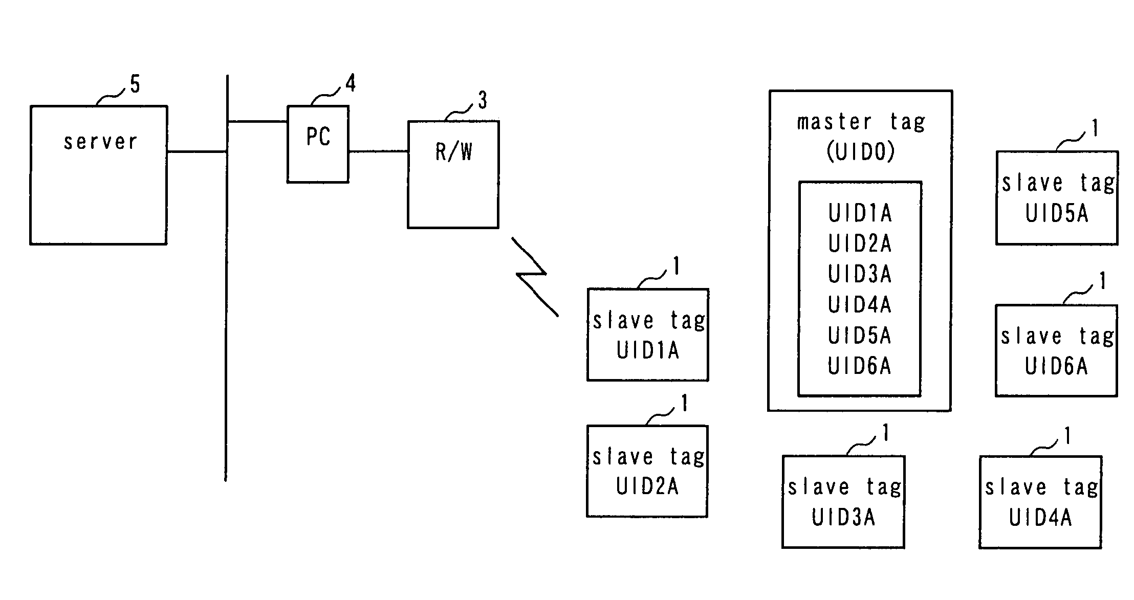
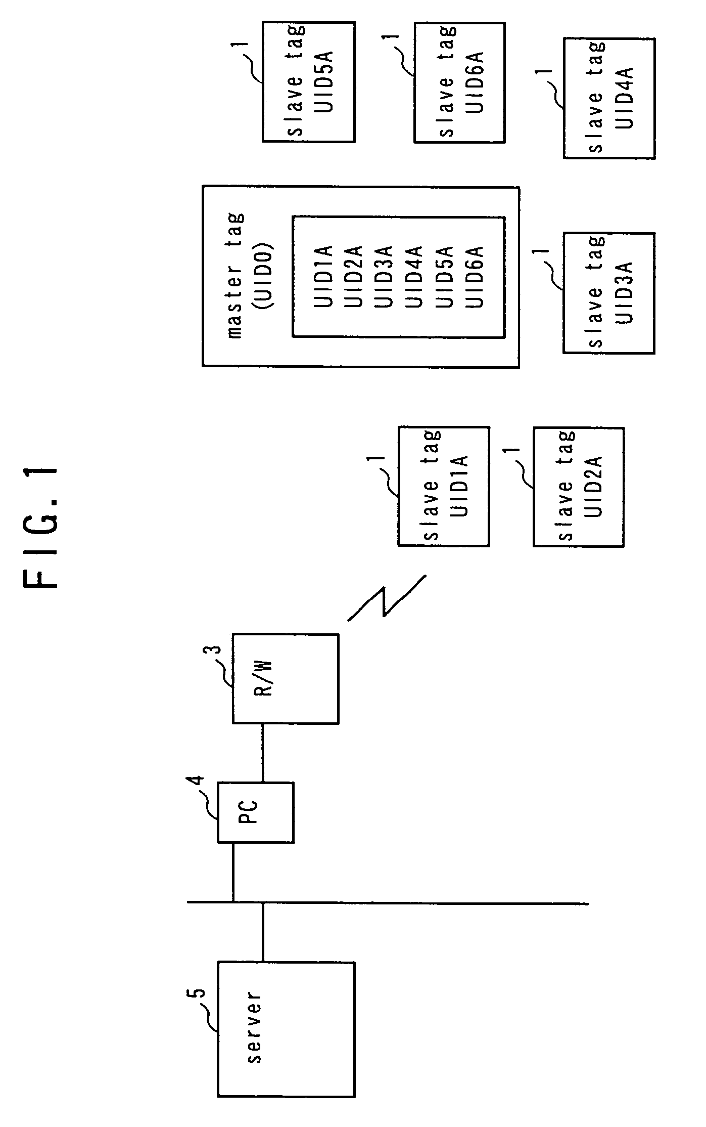
[0064]FIG. 1 is a schematic block diagram of the first embodiment of wireless tag system according to the invention, illustrating the overall configuration thereof. Referring to FIG. 1, the wireless tag system comprises a plurality of slave tags 1, at least a master tag 2 arranged for the plurality of slave tags 1, a read / write device (R / W) 3 adapted to access the master tag 2 and the slave tags 1 and communicate with any of them, a PC 4 that controls the read / write device 3 and a server 5 connected to the PC 4 and adapted to provide the PC 4 with necessary information.

[0065]The plurality of slave tags 1 respectively have their own UIDs (UID1A through UID6A). The master tag 2 stores the UIDs (UID1A through UID6A) of the slave tags 1 and is adapted to transmit the UIDs of all the slave tags 1 in response to a request from the read / write device 3. The read / write device 3 can receive the transmitted UIDs and transfer them to the PC 4. The master tag 2 can delete or re...

second embodiment

[Second Embodiment]

[0074]In the second embodiment, dedicated commands are provided in order to discriminate the access to the master tag and the access to the slave tags.

[0075]FIG. 4 is a conceptual illustration of the second embodiment. In FIG. 4, (a) shows a situation where a single master tag 2 and a plurality of slave tags 1 exist. It is necessary to firstly access the master tag 2 in order to acquire the UIDs of the slave tags stored in the master tag 2. The master tag 2 can be accessed efficiently by separately preparing an access command which accesses the master tag 2 and an access command which accesses the slave tags. This arrangement provides an additional managemental advantage that, when the slave tags need to be accessed, they can be accessed without involving the master tag.

[0076]In FIG. 4, (b) shows an example of command format. With this format, the master tag 2 is selected when the command code is “0x00” so that all the subsequent commands are regarded as those sol...

third embodiment

[Third Embodiment]

[0078]In the third embodiment, group addresses are provided so as to be able to identify the master tag and the slave tags which are accessed.

[0079]FIG. 6 is a conceptual illustration of the third embodiment. FIG. 6(a) shows an example of command format. If the command code is “0x00” and the group address is “10” while the data is “0x80”, it is clearly seen from (b) of FIG. 6 that the data “0x80 ” stored at address “10” is carried by tag B. Thus, it is possible to tell if a given command is for the master tag or for the slave tags by using group addresses as described above to a great advantage of improving the efficiency of management.

[0080]FIGS. 7(a) and 7(b) show flow charts of the operation of the third embodiment. FIG. 7(a) shows a flow chart for the access control device, whereas FIG. 7(b) shows a flow chart for the tags.

[0081]As shown in FIG. 7(a,) when a processing operation is started, the wireless tag access control device determines if the coming communi...


PUM


Abstract

A wireless tag system which does not require any anti-collision process or, if an anti-collision process is required, can reduce the number of tags that need to participate in the anti-collision process to make the anti-collision process proceeds fast. The wireless tag system comprises a plurality of wireless slave tags which have respective unique IDs, a plurality of wireless master tags arranged for the slave tags and storing the unique IDs of the slave tags and a wireless tag access control device which accesses the master tags to acquire the unique IDs of the slave tags from the master tags and subsequently accessing the slave tags by using the acquired unique IDs of the slave tags.

Description

BACKGROUND OF THE INVENTION[0001]1. Field of the Invention[0002]This invention relates to a wireless tag system adapted to communications between a plurality of wireless tags (to be also referred to as IC tags hereinafter) and a read / write device and also to a wireless tag access control device, a wireless tag access control method, a wireless tag access control program and a tag that can be used for such a wireless tag system.[0003]2. Description of Related Art[0004]As a result of the rapid development of IC technologies in recent years, wireless tag systems using ICs have become very popular and are currently spreading very fast (see, inter alia, Patent Document 1: Jpn. Pat. Appln. Laid-Open Publication No. 2003-196360).[0005]With such a wireless tag system, a plurality of wireless tags are attached to respective objects that have to be held under control so that any of the tags can be accessed by way of a read / write device in order to read information from and / or write informatio...

Claims


Application Information

Patent Timeline
Patent Type & Authority Patents(United States)
IPC IPC(8): G08B13/14H04B1/59H04B5/02H04W84/10H04W84/12H04W84/20
CPCG06K7/0008G06K7/10019G06K17/0029G06K19/0723G06K7/00G06K17/00
Inventor HASHIMOTO, SHIGERUHAENO, TADASHI
Owner FUJITSU LTD
Why Eureka
Try Eureka