Automatic camera calibration method

a technology of automatic camera and calibration method, applied in the field of automatic camera calibration method, can solve the problems of many problems, system becomes complicated, and cannot cope with occlusion

Inactive Publication Date: 2007-05-01
ATR ADVANCED TELECOMM RES INST INT
View PDF10 Cites 37 Cited by
  • Summary
  • Abstract
  • Description
  • Claims
  • Application Information

AI Technical Summary

Benefits of technology

[0029]An object of the present invention is to provide an automatic camera calibration method in which all cameras need not share an observation with a reference camera, and a local observation which is not shared with the reference camera can be also utilized for estimating the respective positions and postures of the cameras.
[0030]Another object of the present invention is to provide an automatic camera calibration method capable of easily adding and deleting an observation section in a system for tracking a moving object utilizing a multi-viewpoint image.

Problems solved by technology

For example, they cannot cope with occlusion, and a detection area is narrow.
In order to track human motion in a wide range by such a system, however, a lot of cameras are required in correspondence with detection areas, thereby causing many problems.
For example, a lot of vision systems presuppose that cameras carry out observations at the same time for three-dimensional measurement, and the system becomes complicated by introducing a synchronous mechanism used therefor.
Further, a plurality of observations simultaneously carried out increases redundancy among the observations, thereby reducing the processing efficiency of the system.
Further, it is difficult to previously calibrate all a lot of cameras as the number of viewpoints (the number of cameras) increases.
It is considered that the problems become significant as the number of viewpoints to be utilized increases.
However, the methods cannot be applied to a case where an observation is not shared between a camera to be calibrated and a reference camera.

Method used


Image

  • Automatic camera calibration method
  • Automatic camera calibration method
  • Automatic camera calibration method

Examples


verification experiments

[0179][2-4] Verification Experiments

[0180]In order to assure the effectiveness of the above-mentioned calibration method, the following experiments were conducted.

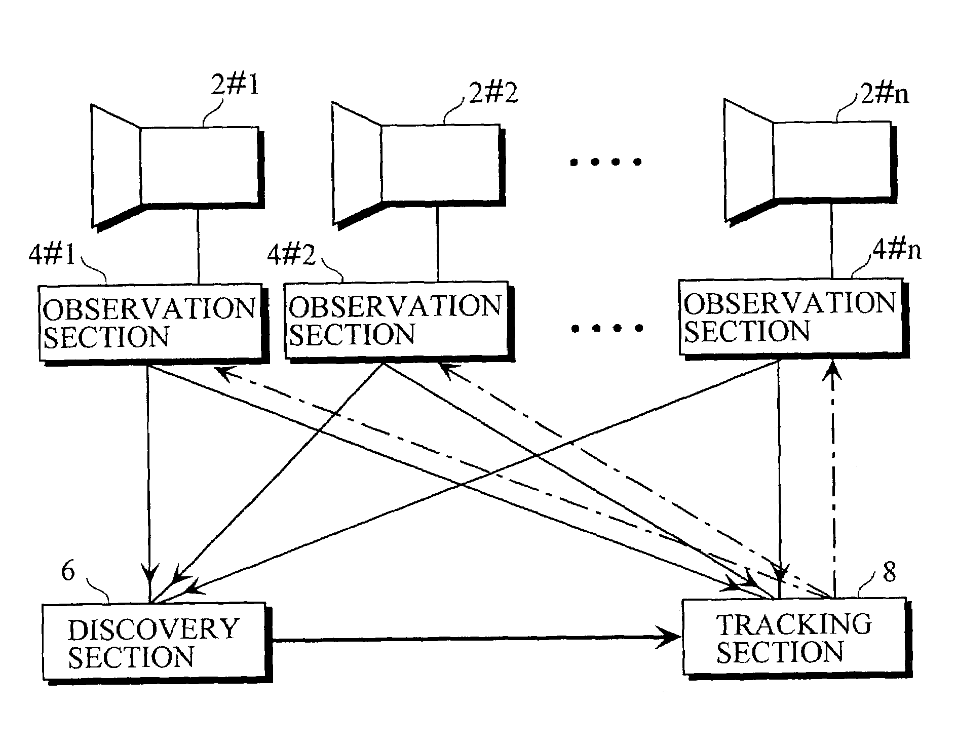
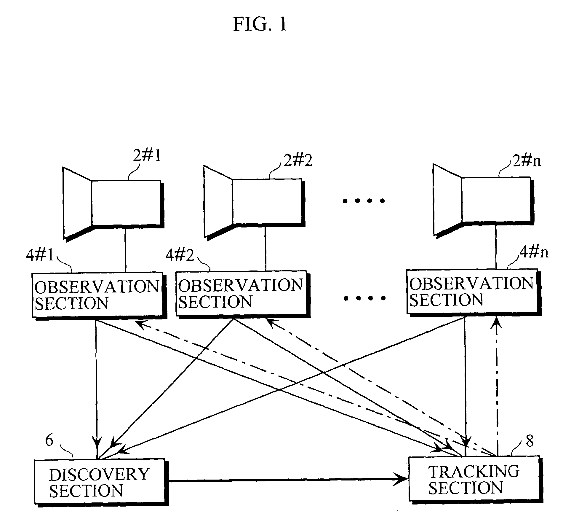
[0181]Five cameras (cameras 1 to 5) were used, to previously give the position and posture of the camera 1 and the position of the camera 2 in order to determine the world coordinate system.

[0182]10000 points were selected at random from a region measuring 150×150×150 [cm] in a scene, and the two cameras were selected at random from the five cameras with respect to each of the points. The two-dimensional observation position and the two-dimensional size were calculated by each of the two cameras, and a Gaussian error was further added to the obtained two-dimensional observation position and two-dimensional size, to respectively find observations in the camera.

[0183]Calibration information related to the position and posture which are stored in each of the cameras was updated by each of the observations.

[0184]FIG. 7 illustr...


PUM


Abstract

In an automatic camera calibration method in a system comprising a plurality of cameras, the automatic camera calibration method is characterized in that for each of the cameras, the estimated values of the position and posture of the camera are updated on the basis of observation information shared with the surrounding cameras and the estimated values of the respective current positions and postures of the surrounding cameras. An example of the observation information is the two-dimensional coordinate value of an image to be observed on an image plane of the camera and the size of the image to be observed.

Description

BACKGROUND OF THE INVENTION[0001]1. Field of the Invention[0002]The present invention relates to an automatic camera calibration method.[0003]2. Description of the Prior Art[0004]The inventors of the present invention have aimed at a non-contact interface with a computer, and have examined a method of detecting human motion by image processing (see the following documents 1, 2, and 3).[0005]Document 1: Hiroki Mori, Akira Utsumi, Jun Ohya, and Masahiko Yachida. Human tracking system using adaptive camera selection. In Proc. of RO_MAN'98, pp. 494–499, 1998.[0006]Document 2: Hiroki Mori, Akira Utsumi, Jun Ohya, and Masahiko Yachida. Examination of method of tracking a plurality of persons using asynchronous multi-viewpoint information. IEICE Technical Report, PRMU98-178, pp. 15–22, 1999.[0007]Document 3: Howard Yang, Akira Utsumi, and Jun Ohya. Stabilization of tracking of a plurality of persons using asynchronous multi-viewpoint image. IEICE Technical Report, PRMU99-150, pp. 1–7, 1999...

Claims


Application Information

Patent Timeline
Patent Type & Authority Patents(United States)
IPC IPC(8): G03B1/00H04N7/18G01S5/16
CPCG01S5/16H04N7/181
Inventor UTSUMI, AKIRAYAMAZOE, HIROTAKE
Owner ATR ADVANCED TELECOMM RES INST INT
Why Eureka
Try Eureka