
Optical scanning arrangement and image forming device with the arrangement

Active Publication Date: 2007-05-01
SHARP KK +1
View PDF11 Cites 0 Cited by
  • Summary
  • Abstract
  • Description
  • Claims
  • Application Information

AI Technical Summary

Benefits of technology

[0012]An object of the present invention is to provide an optical scanning arrangement which can minimize the influence on scanning properties and adjust a scanning position of a scanning beam easily and quickly after installing the optical scanning arrangement in an image forming device, and the image forming device using the optical scanning arrangement.
[0020]Consequently, in view of the necessities of moving the mirror position only in a certain direction and minimizing the influence on images with the movement of the mirror position, a method of moving the mirror position in the parallel direction to adjust the mirror position is preferable in the adjustment performed after the optical scanning unit is installed in the main apparatus.
[0022]Therefore, before the optical scanning arrangement is installed, the first adjustment means can adjust the position of the curved mirror while checking the position of the scanning beam on the scanning target, so that the coarse adjustment of the position of the scanning beam is possible to obtain an excellent image quality. Further, by installing the optical scanning arrangement in the image forming device, the second adjustment means cause the position of the curved mirror to be moved, whereby the fine adjustment can be performed for the positional deviation of the scanning beam caused on the scanning target.
[0023]Especially, the movement direction of the position of the curved mirror by the second adjustment means is the substantially parallel direction to the approximately plane surface of the reflective plane surface of the curved mirror, so that it is possible to minimize the scanning beam's influence on scanning properties and adjust the positional deviation of the scanning beam. Further, in the adjustment by the second adjustment means, the movement in the substantially parallel direction alone can adjust the position of the curved mirror, so that it is not necessary to make the curved mirror move in multi-directions, and easy adjustment is possible.
[0024]As a result of this, it is possible to provide an optical scanning arrangement which can minimize the influence on scanning properties and adjust the scanning position of the scanning beam easily and quickly after installing the optical scanning arrangement in the image forming device.

Problems solved by technology

However, in the conventional optical scanning arrangement, the optical scanning units are adjusted by each unit, resulting in a subtle deviation occurred between the optical scanning units and the scanning target after installing them in a main apparatus.
Because of this, there is a problem of difficulty in fine adjustment.
Further, in case of the tandem apparatus which has the plurality of optical scanning units, there has been a problem of a high cost.
Therefore, in the previous method of adjusting the positions for mounting the optical scanning units for positional deviations of the image carriers, it is impossible to perform the positional adjustment of each optical scanning line corresponding to each image carrier.

Method used


Image

  • Optical scanning arrangement and image forming device with the arrangement
  • Optical scanning arrangement and image forming device with the arrangement
  • Optical scanning arrangement and image forming device with the arrangement

Examples


Embodiment Construction

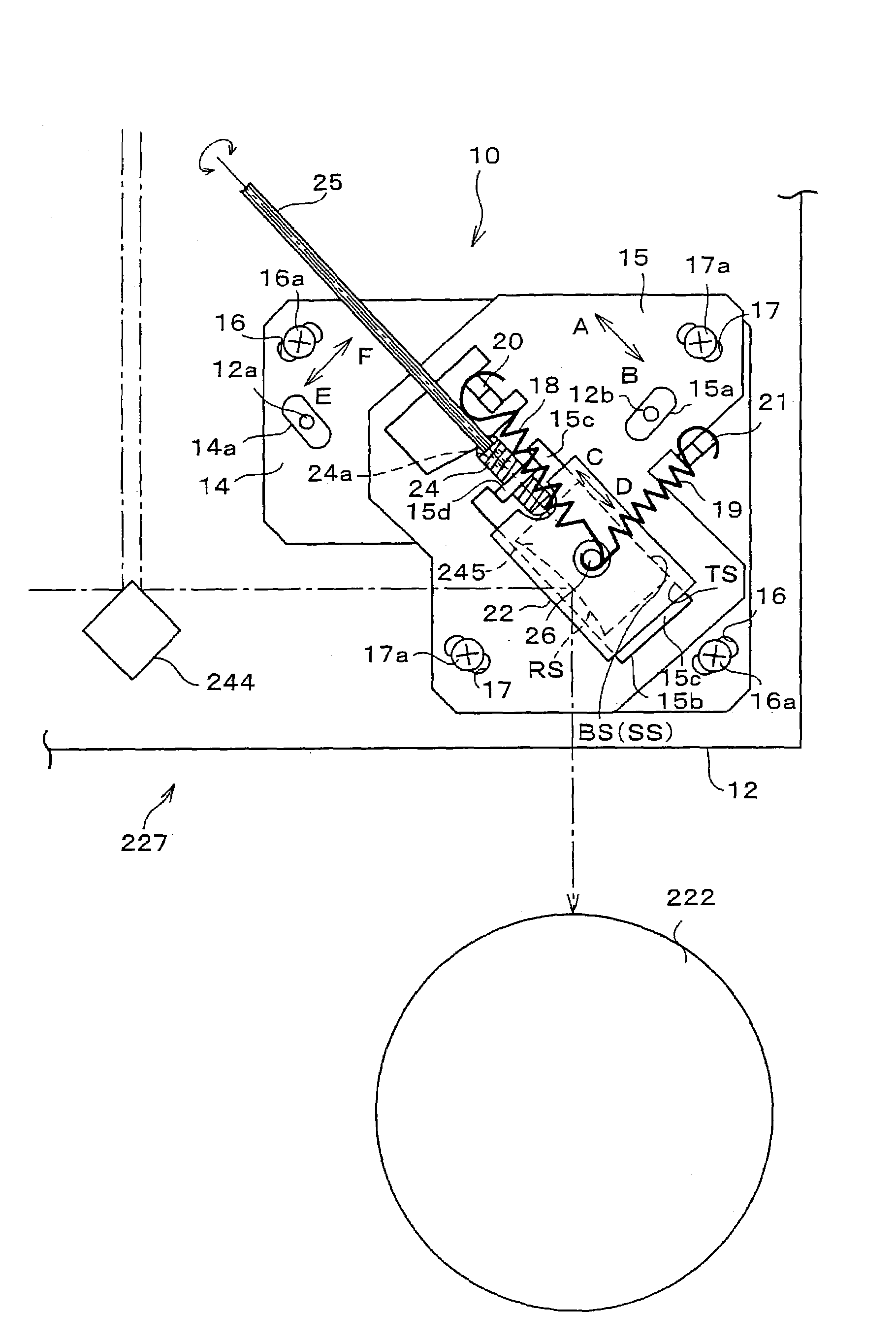
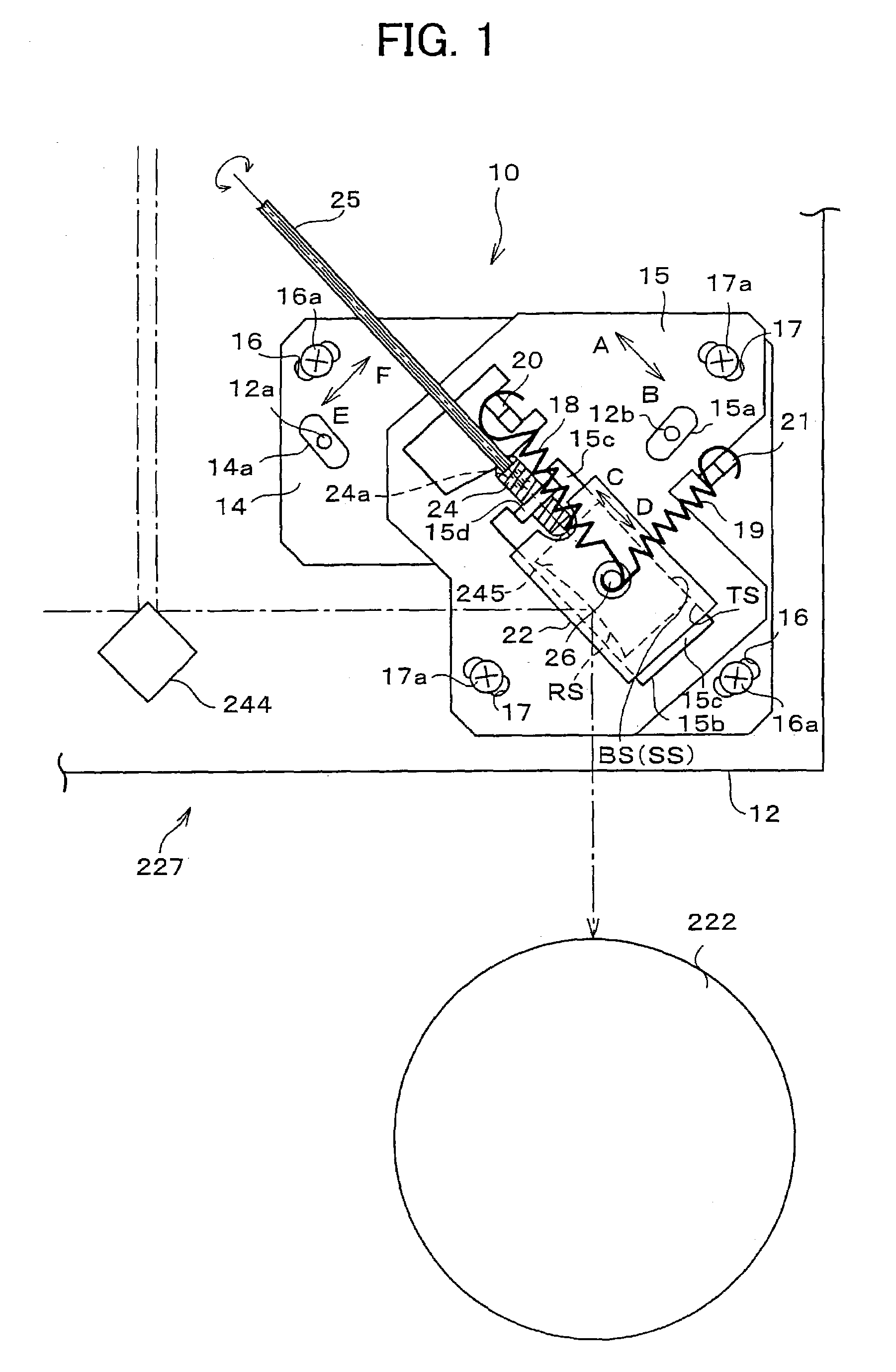
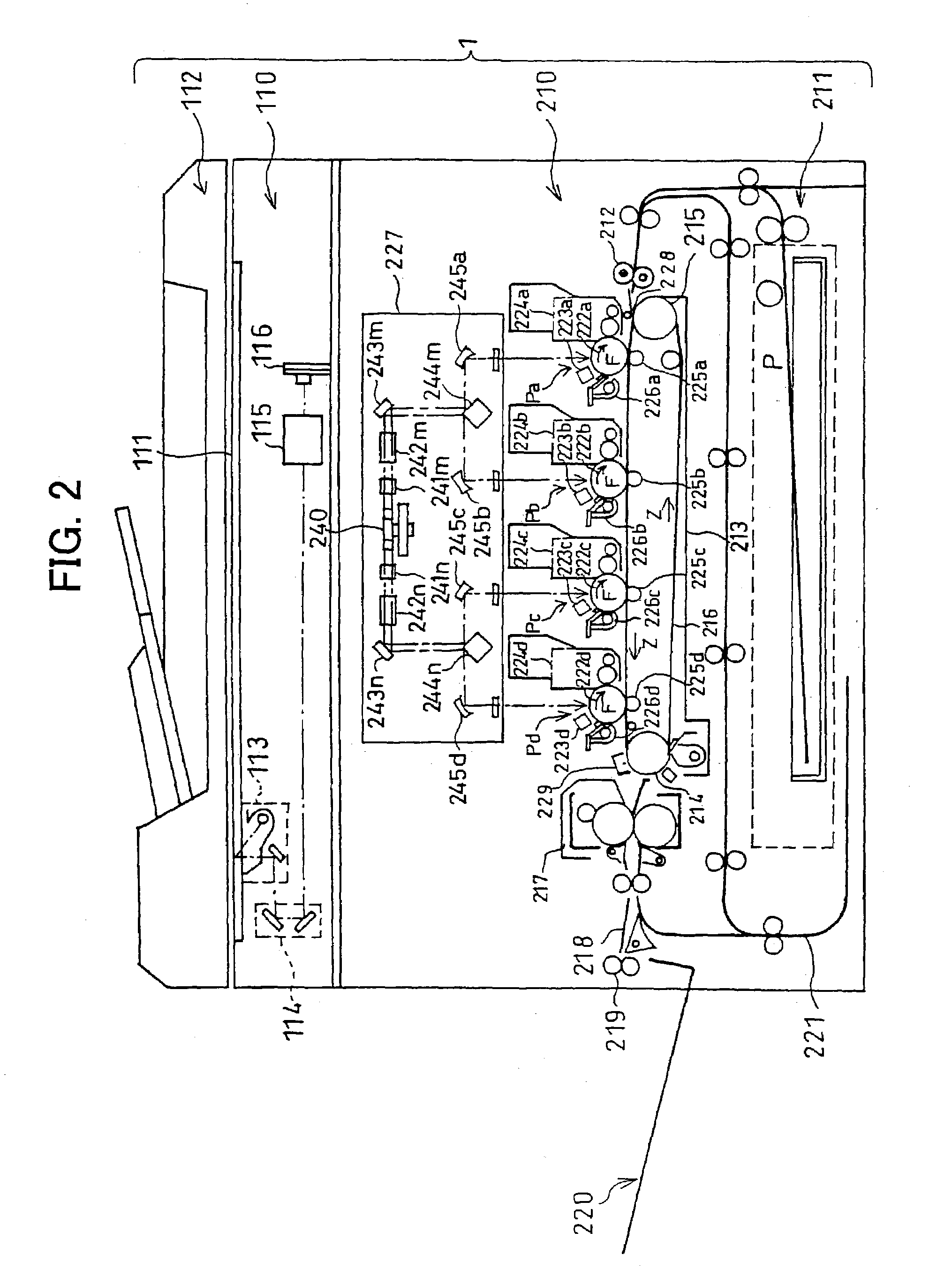
[0033]The following will explain one embodiment of the present invention with reference to FIGS. 1 through 7. Note that, the present invention is not limited to this. Moreover, as an image forming device in the present embodiment, for example, a digital color copying machine in tandem system is described. Incidentally, the image forming device is not necessarily limited to this, and a printer, other copying machine, or a facsimile apparatus may be adopted. Further, in the present embodiment, as the digital color copying machine in tandem system described is a system in which one optical deflecting section scans with a plurality of light beams. However, the digital color copying machine in tandem system is not limited to this, and a system in which a plurality of image carriers and optical scanning units having the number corresponding to the number of the image carriers may be adopted.

[0034]Further, the explanation is carried out in accordance with the order of (1) the whole arrange...


PUM


Abstract

The present invention includes a first plate (14) and a second plate (15) which perform a coarse adjustment of a cylinder mirror (245) by moving the cylinder mirror (245) linearly in the substantially vertical and parallel directions with respect to an appropriate plane surface of a reflective surface (RS) of the cylinder mirror (245), and the second plate (15), a second plate opening section (15b), a setscrew (24), and a hexagon shaft (25) which perform a fine adjustment in the position of the cylinder mirror (245) by moving linearly only in the substantially parallel direction after the coarse adjustment has been completed.

Description

TECHNICAL FIELDS[0001]The present invention relates to an optical scanning arrangement used in an image forming device such as printer, copying machine, and facsimile apparatus which scans and records images on photoconductors in accordance with scanning beams made from optical beams which are modulated based on image data, and the image forming device including the optical scanning arrangement. More particularly, the present invention relates to adjustment means for adjusting scanning positions of scanning beams.BACKGROUND OF THE INVENTION[0002]In an image forming device, e.g. digital copying machine, optical printer, etc., with optical scanning and recording in a conventional electrophotographic system, used is an optical scanning arrangement in which an image carrier such as a photoconductor drum and an optical scanning unit such as an LSU (Laser Scanning Unit) and an LED (Light Emitting Diode) line head are positioned mutually in a predetermined positional relation in a frame of...

Claims


Application Information

Patent Timeline
IPC IPC(8): G02B26/08B41J2/44G02B7/182G02B7/198G02B26/10G02B26/12G02B27/62H04N1/113
CPCG02B7/1824G02B26/126G02B27/62
Inventor YAMANAKA, TOSHIOODA, AYUMUTOMITA, NORIOTAKA, KYOSUKESAKAGAMI, HIDEKAZUOHNO, MITSUHIROORI, TETSUYA
Owner SHARP KK
Features
  • Generate Ideas
  • Intellectual Property
  • Life Sciences
  • Materials
  • Tech Scout
  • Unparalleled Data Quality
  • Higher Quality Content
  • 60% Fewer Hallucinations
Learn More