Eureka AIR delivers breakthrough ideas for toughest innovation challenges, trusted by R&D personnel around the world.

Modulation device, modulation method and recording medium

a modulation method and recording medium technology, applied in the field of modulation devices, modulation methods, recording mediums, etc., can solve the problems of ineffective above copy-protection mechanisms, inability to judge whether or not the optical disc is readable, and copy-right infringemen

Inactive Publication Date: 2007-05-01
JVC KENWOOD CORP
View PDF14 Cites 8 Cited by
  • Summary
  • Abstract
  • Description
  • Claims
  • Application Information

AI Technical Summary

Benefits of technology

[0059]Accordingly, it is desired to provide a modulation device, a modulation method and a recording medium capable of preventing in advance, copy of digital information signals recorded in a recording medium such as an optical disc and a digital magnetic tape by generating a code word sequence without conforming to a predetermined run-length limiting rule but ensuring that an original recording medium on which the code word sequence is recorded can be played back by means of a player that has been commercially available while disabling a copied recording medium, into which the digital information signals are copied, from being played back.

Problems solved by technology

In this situation, when the music information recorded on a CD or the computer data recorded on a CD-ROM is recorded on a CD-R or a CD-RW, the signal format of the CD-R or the CD-RW is the same as the signal format of the CD or the CD-ROM, and therefore the infringement of a copyright occurs.
When playing the modified CD with a commercially available optical disc drive, it is impossible to judge whether or not the optical disc as played is legally-distributed because the verification pit having a length of 1T to 2T in the data as read out is shorter than a normal pit having a pit length (land length) of 3T to 11T and therefore the RF signal as read out by an optical pickup does not reach a sufficient bright level or a sufficient dark level so that the binary signals obtained from the RF signal contains no signal indicative of the verification pit having a length of 1T to 2T.
Accordingly, under the present circumstance in which a number of players and CD-R drives have already been distributed on the market, the above copy-protection mechanism is not effective because of its assumption of the spread of a new player such as the optical disc 100 capable of detecting the verification pit.
Furthermore, in the same manner as optical discs, digital magnetic tapes have the same problem that digital information signals recorded therein are copied.

Method used


Image

  • Modulation device, modulation method and recording medium
  • Modulation device, modulation method and recording medium
  • Modulation device, modulation method and recording medium

Examples


first embodiment

[0117]Described first is the present invention, i.e., a modulation device, a modulation method and a recording medium capable of preventing in advance, copy of digital information signals recorded in a recording medium such as an optical disc and a digital magnetic tape by generating a code word sequence without conforming to a predetermined run-length limiting rule but ensuring that an original recording medium on which the code word sequence is recorded can be played back by means of a player that has been commercially available while disabling a copied recording medium, into which the digital information signals are copied, from being played back.

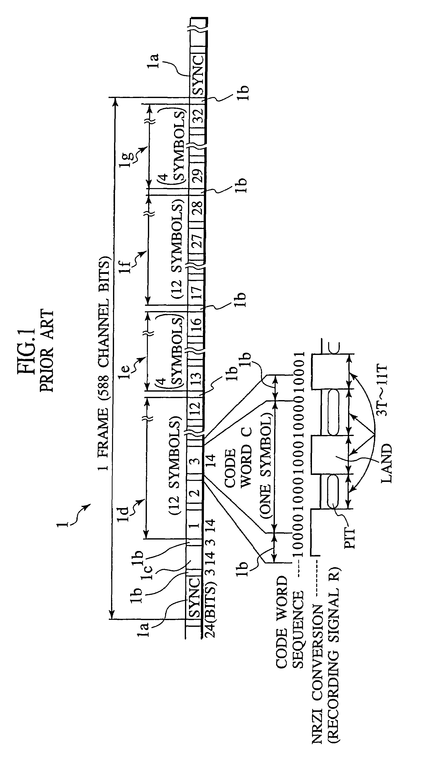
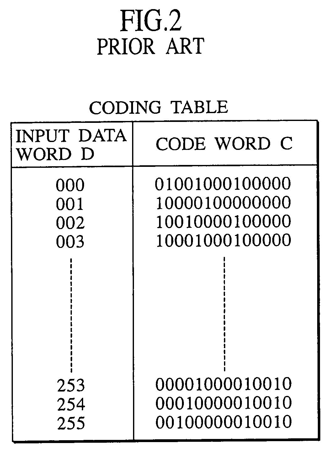
[0118]According to the modulation device, the modulation method and the recording medium of the first embodiment of the present invention applied in conformity with the CD standards for example, EFM signals 1 are generated by converting each input data word of p bits (=8 bits) into a code word C of q bits (=14 bits) and concatenating adj...

second embodiment

[0189]Next, described is the present invention, i.e., a modulation device, a modulation method and a recording medium capable of preventing in advance, copy of digital information signals recorded in a recording medium such as an optical disc and a digital magnetic tape by generating a code word sequence without conforming to a predetermined run-length limiting rule but ensuring that an original recording medium on which the code word sequence is recorded can be played back by means of a player that has been commercially available while disabling a copied recording medium, into which the digital information signals are copied, from being played back.

[0190]In what follows, only the differences of the second embodiment from the first embodiment are described.

[0191]According to the modulation device, the modulation method and the recording medium of the second embodiment of the present invention, when conforming to the CD standards for example, EFM signals 1 are generated by converting...

third embodiment

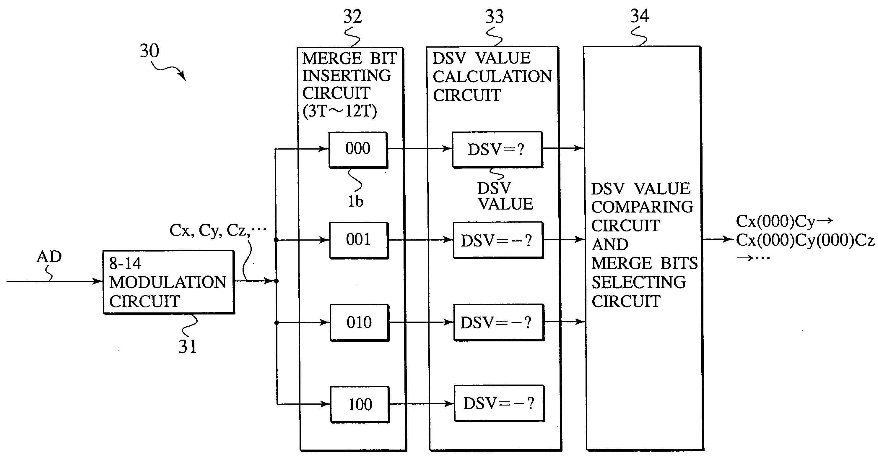
[0242]A modulation device 30b according to the present invention as shown in FIG. 22 is applicable to a glass master disc recording apparatus (not shown in the figure) for producing CDs and generally composed of an 8–14 modulation circuit 31, a first merge bit inserting circuit 32Ab, a first DSV value calculation circuit 33A, a second merge bit inserting circuit 32Bb, a second DSV value calculation circuit 33B, a DSV value comparing circuit and merge bit selecting circuit 34, and a final code word sequence output circuit 35.

[0243]The first and second merge bit inserting circuits 32Ab and 32Bb have the same internal structure, while the first and second DSV value calculation circuits 33A and 33B have the same internal structure. It is therefore possible, depending upon by the software for taking control of the modulation device 30 according to the third embodiment, to use only one merge bit inserting circuit functioning as the first and second merge bit inserting circuits 32Ab and 32...


PUM

PropertyMeasurementUnit
thicknessaaaaaaaaaa
diameteraaaaaaaaaa
diameteraaaaaaaaaa

Abstract

When a code word sequence is generated by converting input data words of p bits into code words of q bits and concatenating adjacent ones of the code words with a merge bit sequence of r bits in order to obtain the best DSV value, according to one aspect, the adjacent code words are concatenated with the merge bit sequence of r bits which is selected, free from the restriction of the minimum run-length of (d+1)T and the maximum run-length of (k+1)T based on the run-length limiting rule RLL(d, k) but permitting the minimum run-length of (d+1)T and the maximum run-length of (k+2)T. According to another aspect, a merge bit sequence to be inserted after a current code word is selected by prefetching the current code word, a next code word, and a further next code word, temporarily concatenating these code words with merge bit sequences of r bits respectively to prepare code word sequence candidates free from the predetermined run-length limiting rule, calculating the DSV values of the code word sequence candidates, selecting one of the code word sequence candidates having a DSV value whose absolute value is closest to zero, and selecting the merge bit sequence between the current code word and the next code word of the selected merge bit sequence candidate. According to a further aspect, the input data words are encoded by a p-q modulation scheme after introducing for a predetermined period, as an input data word, specific data comprising alternating current signals or direct current signals which would cause a modulation device that prefetches only the next code word to output a code word sequence which includes particular frequency components.

Description

BACKGROUND OF THE INVENTION[0001]1. Field of the Invention[0002]The present invention is related to a modulation device, a modulation method, and a recording medium for preventing the copy of digital information signals that are recorded on an optical disc, a digital magnetic tape and the like recording medium.[0003]2. Description of the Related Art[0004]With the advent of the digital multimedia age, large amounts of digital information signals are recorded on optical discs, digital magnetic tapes and the like.[0005]For example, a read-only optical disc, such as CD (Compact Disc) for recording music information, CD-ROM (CD-Read Only Memory) for recording computer data, comprises a disc substrate in the form of a platter in which spiral or concentric tracks are defined. A variety of digital information signals can be recorded on the tracks and quickly accessed from the tracks, while the discs are suited to mass-production at a low price, and therefore, such discs have been heavily us...

Claims


Application Information

Patent Timeline
Patent Type & Authority Patents(United States)
IPC IPC(8): G11B20/10H03M7/00G11B7/0045G11B20/14H03M5/14
CPCG11B20/1426H03M5/145G11B2020/1461G11B2020/1469
Inventor KOBARI, HARUKUNIKUROIWA, TOSHIOOHNO, HIROTOSHIYOSHIKAWA, HIROYOSHIOCHI, NOBUCHIKASUZUKI, JUNZO
Owner JVC KENWOOD CORP
Why Eureka
Eureka Blog
Learn More