Disk media, and method of and device for recording and playing back information on or from a disk media

a technology of disk media and information, applied in the field of disk media, can solve the problems of long time delay between image signal reproduction and input data, inability to observe copying degradations, and delay in image signal reproduction and display, etc., to achieve fast playback, shorten the time taken, and reproduce consecutive i pictures smoothly

Inactive Publication Date: 2007-05-01
MITSUBISHI ELECTRIC CORP
View PDF44 Cites 10 Cited by
  • Summary
  • Abstract
  • Description
  • Claims
  • Application Information

AI Technical Summary

Benefits of technology

[0043]Another object of the present invention is to enable high high-speed retrieval of any of I, P, and B pictures during image retrieval.
[0208]With the above arrangement, the start positions of I pictures of image information blocks always coincide with specific positions on an optical disk. The randomness of a rotation wait time associated with a track jump during fast playback or retrieval can therefore be eliminated.

Problems solved by technology

Since this kind of disk filing system handles digital information, degradations due to copying are not observed.
Moreover, a delay time from the input of data to image reproduction is longer.
Accordingly, the reference picture data used for coding P and B pictures in the GOP read first is missing, and image obtained by decoding them would be unnatural, so that they would not be used for playback of the image.
Moreover, with the conventional video disk recording / playback device or playback device, it is not possible to identify the video disk being recorded or played back, so that images to be retrieved, images from which the playback should starts, and the like are not known.
Accordingly, it is not used, and as a result, there is a time delay before the image signal is reproduced and displayed.
Even if the reproduction is forcibly made, a resultant image would be unnatural.
It is not possible to utilize, for recording and playback, vacant sectors which result by repeating erasure and recording.
Thus, the recording regions on the disk are not effectively utilized.
It is therefore not possible to promptly identify the sector where the desired GOP is recorded, and there is a certain time delay before the image signal is reproduced.
Moreover, where the image signal of each GOP is recorded with a variable data rate, the time from the start of the sequence and the recording position are not proportional, so the prediction of the sector address of the sector where the GOP of the desired time instant is recorded is difficult, and there is a further delay before the image signal is reproduced.
When it is taken into account that human eyes are sensitive to what is called a “scene change;” such as a change in strength of a luminance signal, the fast playback or retrieval is not always satisfactory to viewers.
When a track jump is made, it is difficult to specify a start position of an I picture of each GOP.
Every time a jump is made to another track, a random rotation wait time arises, and consecutive reproduction of I pictures cannot be made smoothly.
Furthermore, the speed of fast playback or retrieval cannot be raised in harmony with human visual characteristics.

Method used


Image

  • Disk media, and method of and device for recording and playing back information on or from a disk media
  • Disk media, and method of and device for recording and playing back information on or from a disk media
  • Disk media, and method of and device for recording and playing back information on or from a disk media

Examples


embodiment a1

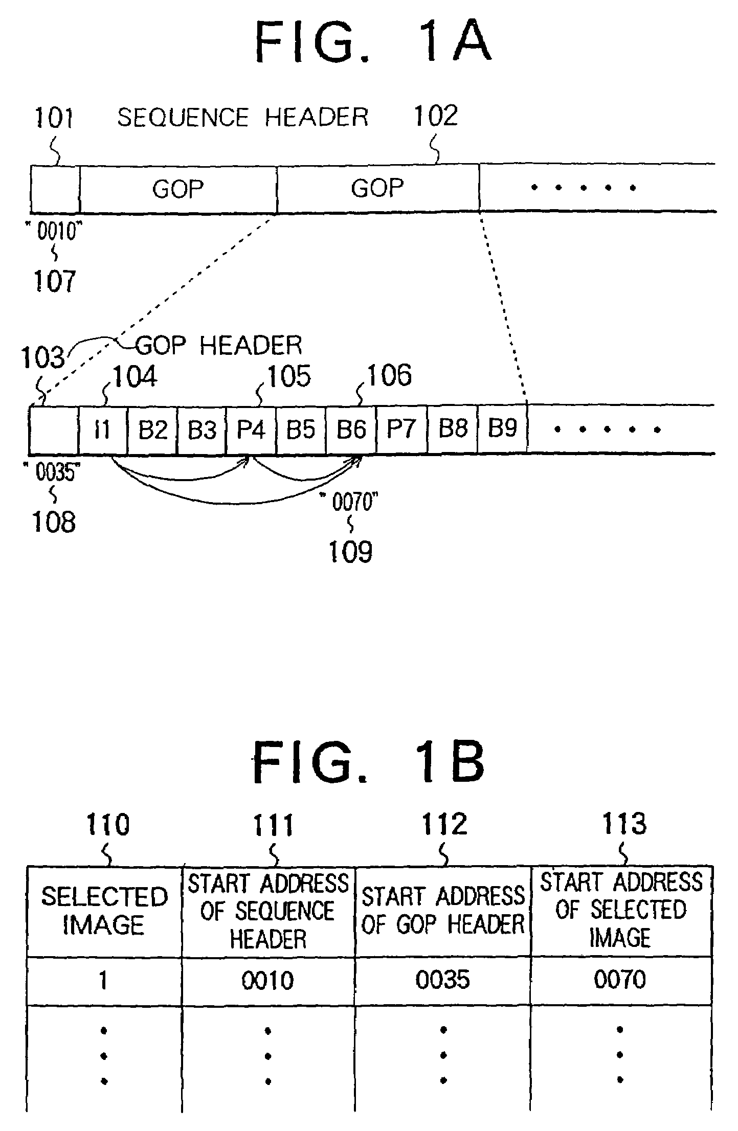
[0263]FIG. 1A and FIG. 1B are diagrams for explaining a video disk recording / playback method of Embodiment A1. FIG. 1A is a schematic diagram showing the data structure of coded data recorded on a video disk. Reference numeral 101 denotes a sequence header. 102 denotes a GOP. 103 denotes a GOP header. 107 denotes the start address of the sequence header 101. 108 denotes the start address of the GOP header 103. 109 denotes the start address of a B6 picture.

[0264]FIG. 1B is a schematic diagram showing an image information table recorded on the video disk. Reference numeral 110 denotes a column in which selected image numbers assigned to the respective selected images are written. 111 denotes a column in which start addresses of sequence headers concerning sequences each containing a selected image are written. 112 denotes a column in which start addresses of GOPs each containing a selected image are written. 113 denotes a column in which start addresses of coded data representing sele...

embodiment a2

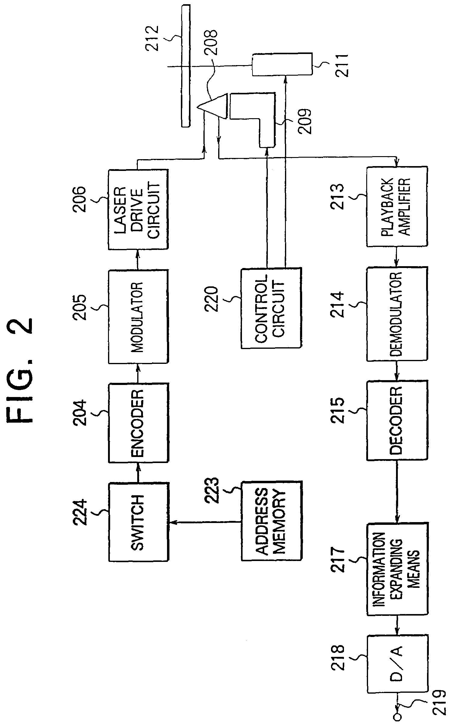
[0273]FIG. 2 is a block circuit diagram showing a video disk recording / playback device of Embodiment A2. As illustrated, it comprises an encoder 204, a modulator 205, a laser drive circuit 206, a control circuit 220, an optical head 208, an actuator 209, a disk motor 211, an optical disk 212, an address memory 223 for storing the start addresses of coded data representing selected images such as images to be retrieved and the start addresses of data including information required for decoding the coded data, and a switch 224 to be manipulated for recording the contents of the address memory 223 into the optical disk 212 at a user's desired time instant.

[0274]The device further comprises a playback amplifier 213, a demodulator 214, a decoder 215, an information expanding means 217, and a D / A converter 218 which outputs an output image signal 219.

[0275]Next, the operations will be described. High-efficiency coded data representing an image and having the GOP structure described in con...

embodiment a3

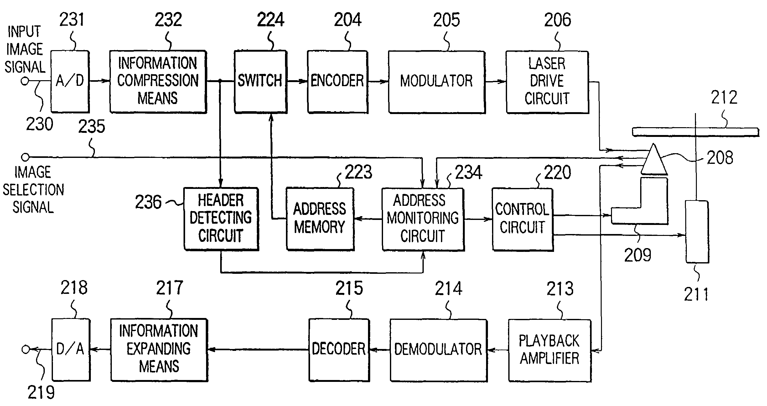
[0282]FIG. 4 is a block circuit diagram showing a video disk recording / playback device of Embodiment A3. The reference numerals identical to those in FIG. 2 denote identical or corresponding parts. It additionally comprises an A / D converter 231 receiving an input image signal 230, an information compressing means 232, an address monitoring circuit 234 receiving an image selection signal 235 indicating that an image has been selected, and associating coded data with an address on the video disk 212, and a header detecting circuit 236 for detecting a GOP header and sequence header in the bit stream of coded data. A switch 424 is provided for changing a signal to be recorded on the optical disk 212 from the input image signal 230 to a signal representing the contents of the address memory 223 or vice versa at, for example, a user's desired time instant.

[0283]Next, the operations will be described. The input image signal 2330 having the GOP structure that has been described in conjuncti...


PUM

PropertyMeasurementUnit
timeaaaaaaaaaa
lengthaaaaaaaaaa
luminanceaaaaaaaaaa

Abstract

In a video disk recording / playback device for converting a digital video signal or the like into high-efficiency coded data and recording the coded data on a video disk, or for restoring high-efficiency coded data recorded on the video disk and reproducing an output image, wherein said digital video signal is composed of a succession of video signals of a plurality of frames and including an I picture encoded within a frame, a P picture interframe coded by forward motion compensation with reference to said I picture and / or another P picture, and a B picture interframe coded by motion compensation in both directions with reference to said I and / or P pictures temporally preceding and succeeding the B picture, there are further provided a means for recording in an image information table set up on said video disk all of the start addresses of coded data representing selected images such as images to be retrieved and the start addresses of data containing information required for reproducing the coded data. With the above configuration, retrieval of all kinds of images of I, P, and B pictures is possible by recording all of the start addresses of coded data representing selected images such as images to be retrieved and the start addresses of data containing information required for reproducing the coded data in the image information table on the video disk.

Description

[0001]This application is a Divisional of co-pending Application Ser. No. 10 / 011,284, filed on Dec. 11, 2001; which is a divisional of prior application Ser. No. 09 / 327,953 filed on Jun. 8, 1999, which issued as U.S. Pat. No. 6,539,164 on Mar. 25, 2003; which is a divisional of Application Ser. No. 08 / 887,929 filed on Jul. 3, 1997, which issued as U.S. Pat. No. 5,949,953 on Sep. 7, 1999; which is a divisional of Application Ser. No. 08 / 539,339 filed on Oct. 4, 1995, which has been abandoned, and for which priority is claimed under 35 U.S.C. § 120; and this application claims priority of Application Nos. 6-245618 filed in Japan on Oct. 11, 1994; 6-265421 filed in Japan on Oct. 28, 1994; 6-276542 filed in Japan on Nov. 10, 1994; and 6-296697 filed in Japan on Nov. 30, 1994 under 35 U.S.C. § 119; the entire contents of all are hereby incorporated by reference.BACKGROUND OF THE INVENTION[0002]The present invention relates to a disk media, such as a video disk or optical disk for recordi...

Claims


Application Information

Patent Timeline
Patent Type & Authority Patents(United States)
IPC IPC(8): H04N5/76H04N5/00H04N7/00H04N7/26G11B7/0037G11B20/10G11B20/12G11B27/036G11B27/10G11B27/11G11B27/28G11B27/30G11B27/32H04N5/85H04N9/804H04N9/82H04N9/87
CPCG11B20/1217G11B27/036G11B27/105G11B27/11G11B27/28G11B27/3027G11B27/324G11B27/326G11B27/329H04N9/8042G11B7/0037G11B20/10G11B2220/20G11B2220/2545G11B2220/65H04N5/85H04N9/8205H04N9/87
Inventor SHIRAKAWA, KOUICHIKASEZAWA, TADASHINAGASAWA, MASATOKIYOSE, YOSHIHIROOHATA, HIROYUKIMISHIMA, HIDETOSHIASAMURA, YOSHINORI
Owner MITSUBISHI ELECTRIC CORP
Why Eureka
Try Eureka