Electric wave receiving apparatus

一种电波接收、电波的技术,应用在电波接收装置领域,能够解决长的时间、难高速切换、等待一定时间等问题

Active Publication Date: 2009-01-21
CASIO COMPUTER CO LTD
View PDF4 Cites 6 Cited by
  • Summary
  • Abstract
  • Description
  • Claims
  • Application Information

AI Technical Summary

Problems solved by technology

[0009] However, in a receiving device that uses a plurality of variable filters configured by connecting a plurality of filter circuits with different pass frequency bands in parallel to switch the receiving channel, it is difficult to switch the receiving channel at high speed and search for the receiving channel without any tricks. Dealing with subjects that take a very long time
[0010] That is, in the receiving circuit, in order to keep the demodulated signal level constant, the received signal is usually amplified by automatic gain control (AGC), but the AGC circuit has a relatively large time constant characteristic, and when switching the receiving channel , it takes several seconds to about ten seconds until the automatic gain control stabilizes
Therefore, when the receiving channel is changed by switching the variable filter, it takes a certain amount of time until a stable detection signal is obtained, and it takes a long time to search for signals of all receiving channels.

Method used


Image

  • Electric wave receiving apparatus
  • Electric wave receiving apparatus
  • Electric wave receiving apparatus

Examples


no. 1 approach

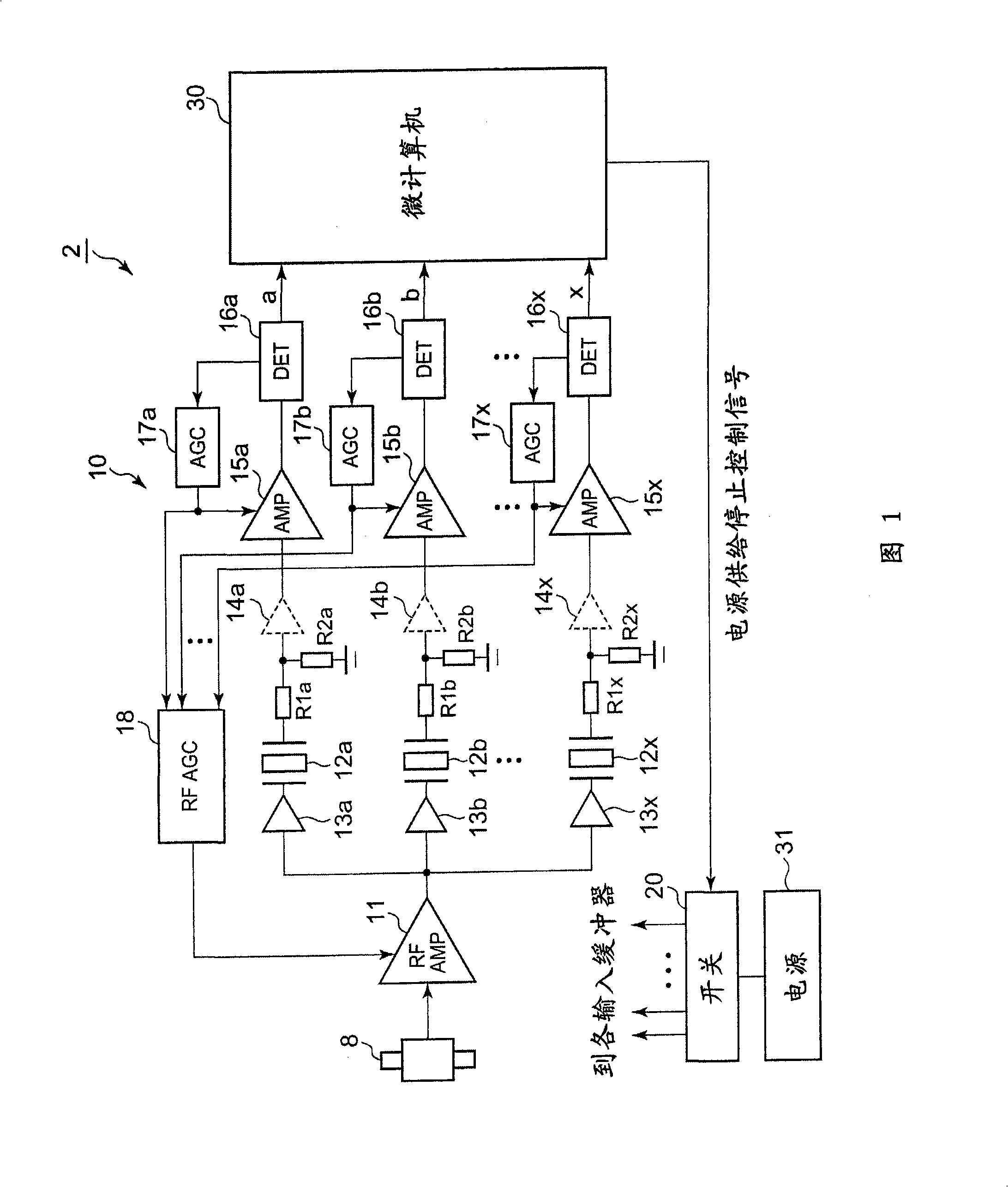
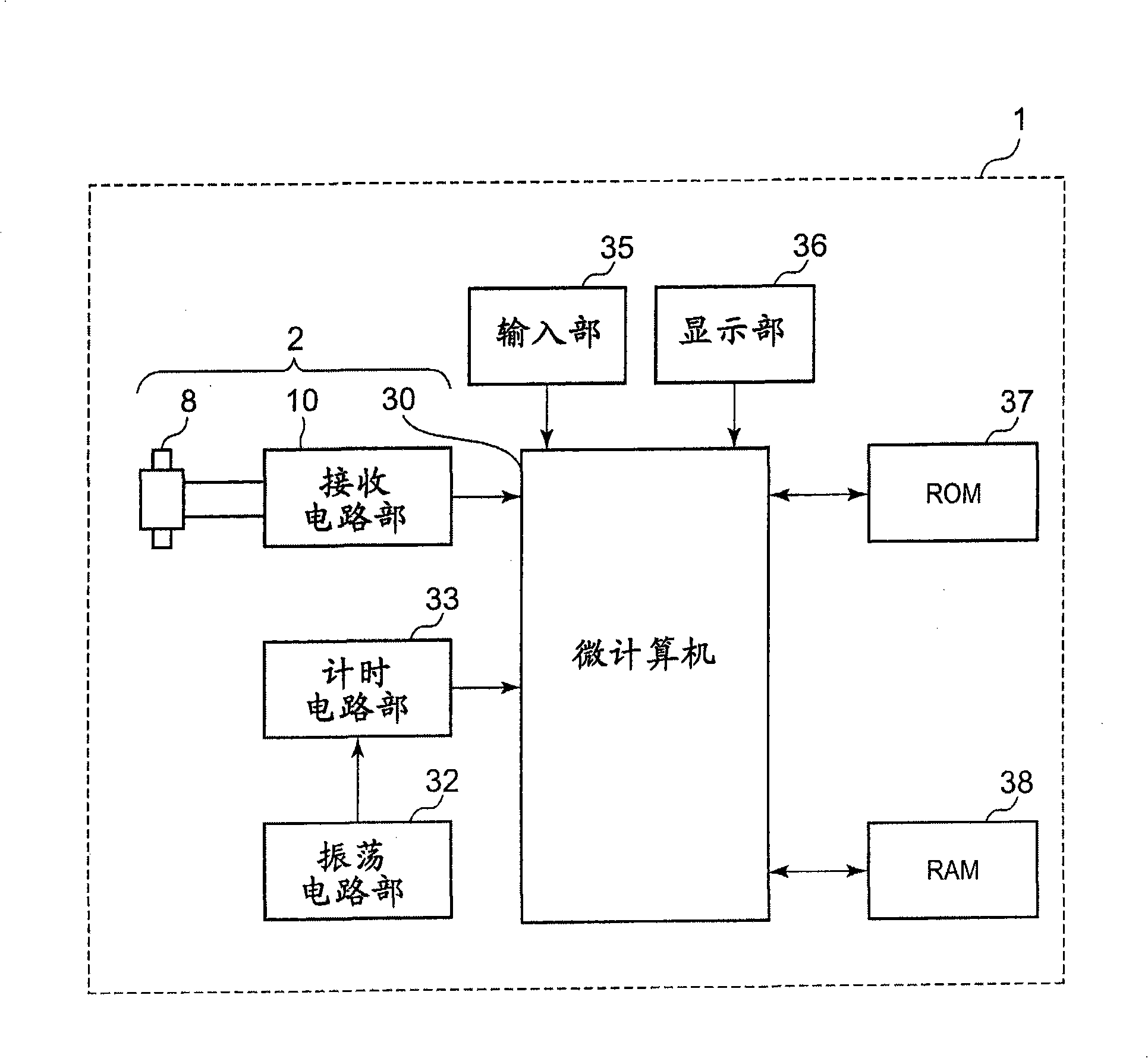
[0027] 1 is a block diagram showing a circuit configuration of a radio wave receiving device 2 according to a first embodiment of the present invention, figure 2 It is a block diagram showing the overall configuration of a radio-controlled timepiece equipped with the receiving circuit unit shown in FIG. 1 .

[0028] The radio wave receiving device 2 of the first embodiment is a device for receiving standard radio waves including time codes transmitted in Japan or other countries, and is mounted on the radio-controlled watch 1 that automatically adjusts the time by the standard radio waves.

[0029] Such as figure 2 As shown, the radio wave receiving device 2 of the first embodiment is composed of a standard radio wave antenna 8 formed by winding a coil around a core material, a receiving circuit unit 10 for receiving a time code, and a received time code. The code analysis microcomputer 30 constitutes.

[0030] As shown in FIG. 1, the receiving circuit unit 10 has: an RF amp...

no. 2 approach

[0061] FIG. 6 is a block diagram showing a circuit configuration of a radio wave receiving device 2B according to a second embodiment of the present invention.

[0062] The radio wave receiving device 2B of the second embodiment is a device having a tuning frequency switching circuit 22 for changing the tuning frequency of the antenna 8, and other configurations are substantially the same as those of the device of the first embodiment. Moreover, although the selection switch 20 which supplies or cuts off the power supply voltage to the buffer circuits 13a, 13b-13x is also omitted from illustration, this selection switch 20 is provided similarly to 1st Embodiment.

[0063] The tuning frequency switching circuit 22 is composed of, for example, a plurality of capacitive elements that can be connected in parallel at both ends of the coil of the antenna 8, a semiconductor switch that turns on / off the connection of the capacitive elements, and the like. The tuning frequency of the ant...


PUM


Abstract

An electric wave receiving apparatus comprises: an antenna receiving electric wave; an RF amplifier; filter circuits that extract signals in different frequency bands; detector circuits correspondingly set to filter circuits; AGC circuits; a micro computer inputted a plurality of wave detection outputs for analysis, wherein the biggest AGC signal selected by RF-AGC circuit is supplied to a RF amplifier to carry out signal level control to wave detection output, and the micro computer searches receiving channel capable of receiving time code based on each wave detection output.

Description

[0001] Cross References to Related Applications [0002] This application is based on and claims priority from prior Japanese Patent Application No. 2007-188317 filed on July 19, 2007, the entire contents of which are hereby incorporated by reference. technical field [0003] The present invention relates to a radio wave receiving device for receiving radio waves including time codes. Background technique [0004] In recent years, with the MEMS (Micro Electro Mechanical Systems) technology, it is possible to form a high-precision filter circuit with a small mounting area and a narrow signal passband. Therefore, by arranging a plurality of filter circuits having different passbands in parallel and using a variable filter used by switching the filter circuit for receiving signals, it is possible to configure a radio wave receiving circuit that can selectively receive signals of a plurality of reception channels. [0005] In addition, as a technique related to the present inve...

Claims


Application Information

Patent Timeline
Patent Type & Authority Applications(China)
IPC IPC(8): H04B1/00H04B1/16G04G5/00G04G9/02G04R20/00G04R20/10G04R20/12H03J5/24
CPCG04G21/04H04B1/24
Inventor 染谷薰
Owner CASIO COMPUTER CO LTD
Why Eureka
Try Eureka