Closure device

a technology of closure device and closure plate, which is applied in the direction of flexible container closure, snap fastener, buckle, etc., can solve the problems of difficult to determine whether the fastening strip is fully occluded, the problem is particularly acute, and the fastening strip is particularly difficult to manipulate or handle by individuals with limited manual dexterity. , to achieve the effect of reliable operation and use, simple and economical construction

Inactive Publication Date: 2007-05-08
THE GLAD PROD CO
View PDF30 Cites 19 Cited by
  • Summary
  • Abstract
  • Description
  • Claims
  • Application Information

AI Technical Summary

Benefits of technology

[0010]A further object of the present invention is to provide a closure device as characterized above which operates in a simple and economical manner.
[0011]An additional object of the

Problems solved by technology

With such closure devices, however, it is often difficult to determine whether the fastening strips are fully occluded.
This problem is particularly acute when the fastening strips are relatively narrow.
Such fastening strips are particularly difficult to manipulate or handle by individuals with limited manual dexterity.
While the use of a slider certainly facilitates the opening and closing of interlocking fastening str

Method used


Image

  • Closure device
  • Closure device
  • Closure device

Examples


first embodiment

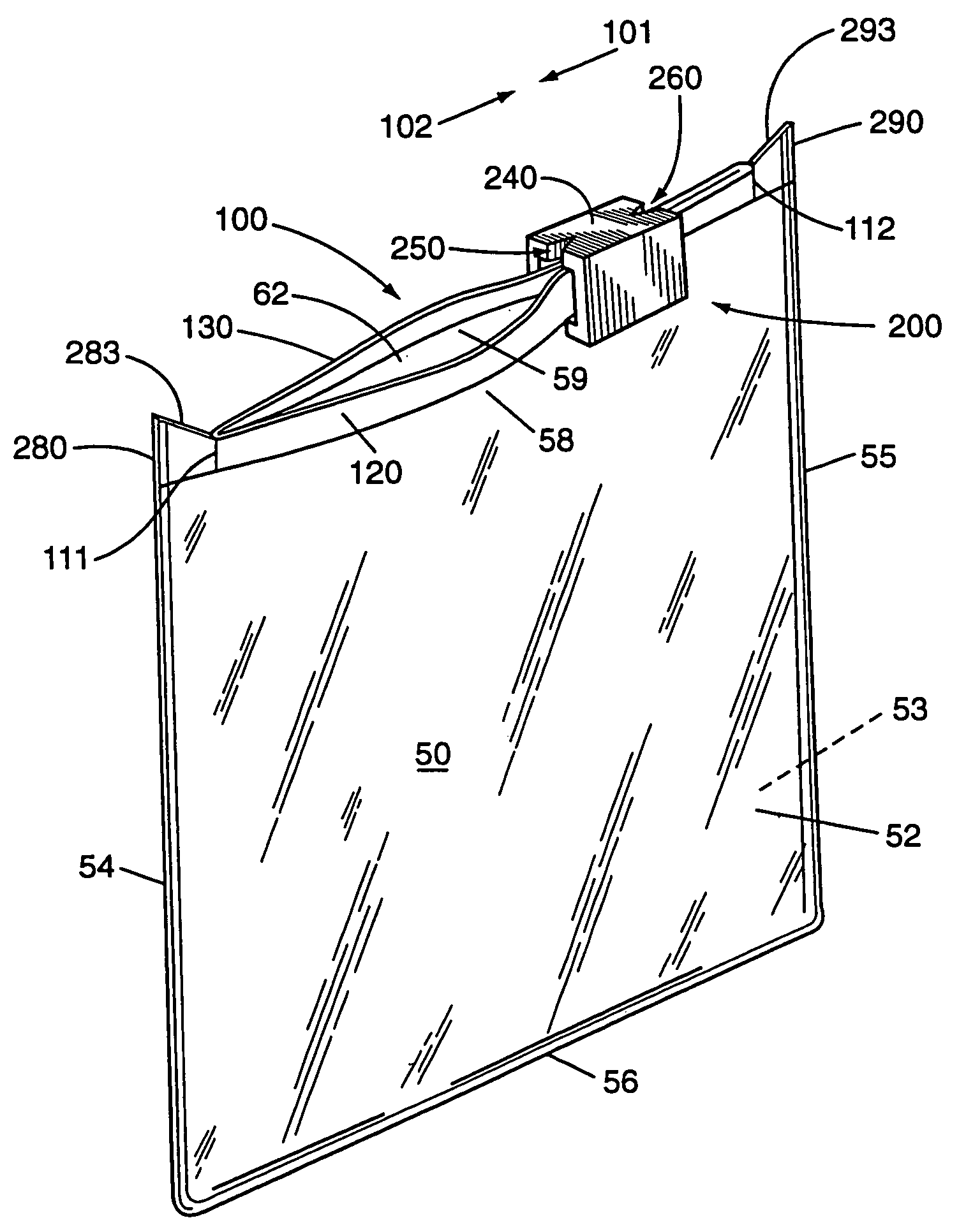
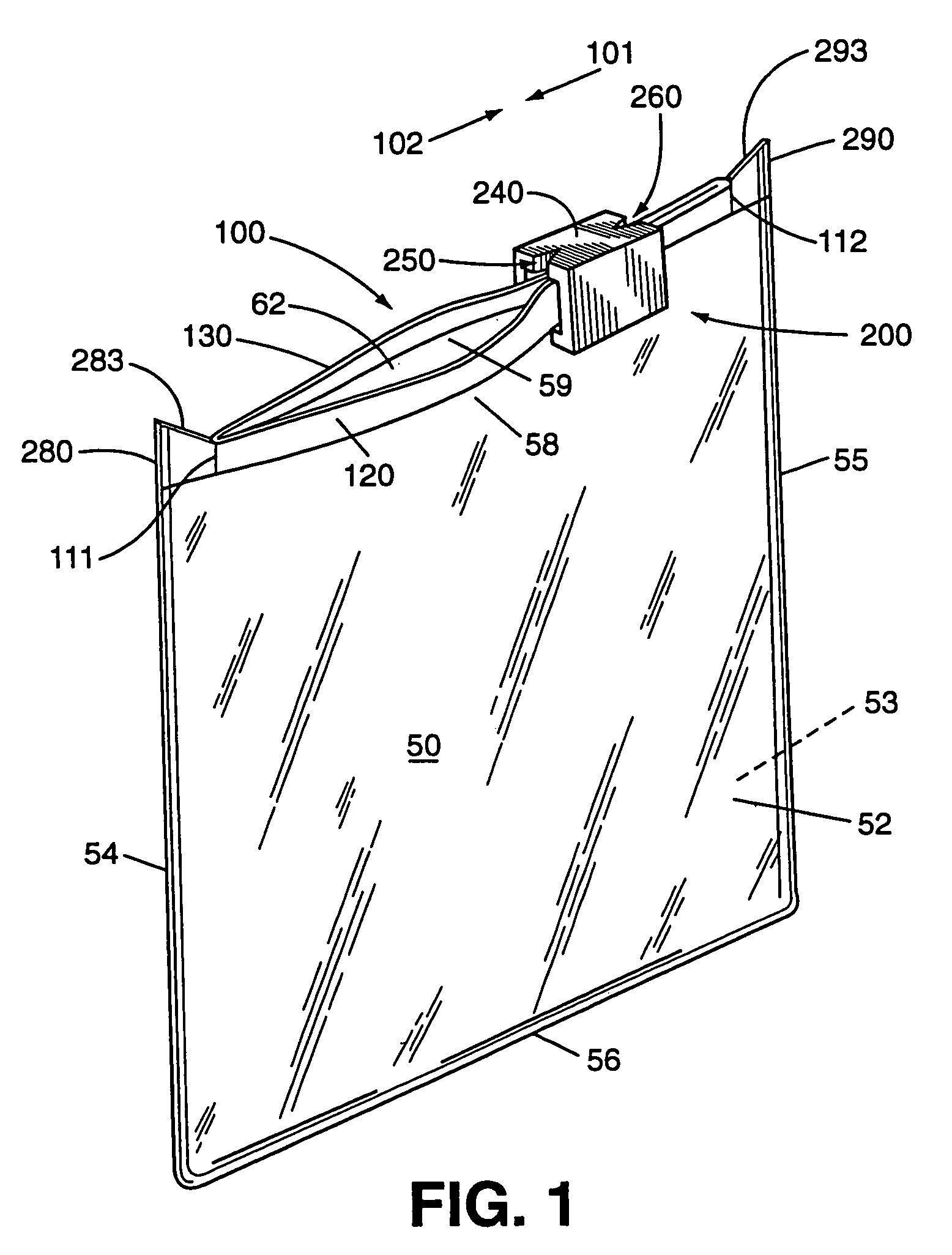
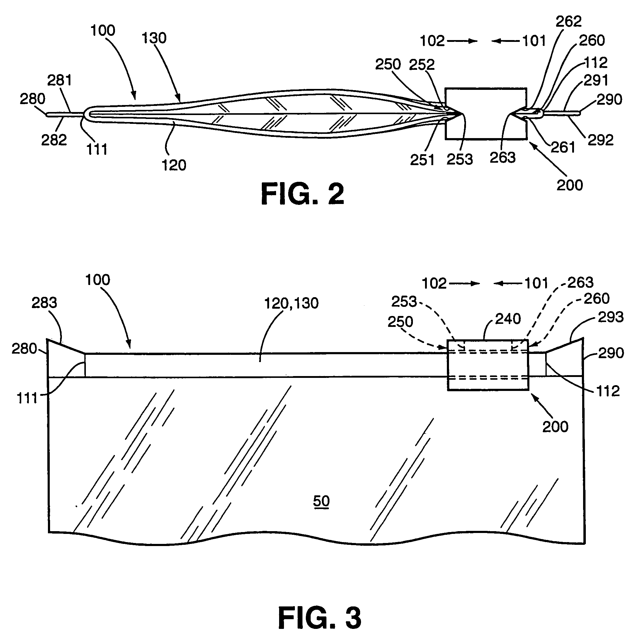
[0036]In a first embodiment, a pair of notches 250, 260 are formed in the intermediate body portion 240 of slider member 200 at opposite ends thereof, as shown, for example, in FIGS. 1–6. These notches 250, 260 are adapted to cooperatively engage a pair of protrusions 280, 290 formed on the interlocking fastening strips 120, 130 at the first and second ends 111, 112 thereof. In this embodiment, the notches 250, 260 are generally V-shaped or triangular in configuration when viewed from above, as shown in FIGS. 2 and 4, and the cooperating protrusions 280, 290 are generally planar or flat in configuration.

[0037]The two generally V-shaped notches 250, 260 each extend through the intermediate body portion 240 of the slider member 200, as shown, for example, in FIG. 1. In addition, the two notches 250, 260 each have a pair of opposed interior sides or faces 251, 252, 261, 262 which converge along generally vertical internal corners 253, 263, as shown in FIGS. 2–5. In this embodiment, the...

third embodiment

[0044]In a third embodiment, a pair of partially curved notches 450, 460 are formed in the intermediate body portion of slider member 400, as shown, for example, in FIG. 10. In this embodiment, each notch 450, 460 includes a pair of spaced-apart interior sides or faces 451, 452, 461, 462 with an intermediate arcuate portion 453, 463 located internally therebetween. While other configurations are permissible and would certainly fall within the scope and spirit of the present invention, the opposed interior sides 451, 452, 461, 462 of the illustrated notches 450, 460 are substantially parallel with respect to each other.

[0045]In usage, the notches 450, 460 of the slider member 400 are adapted to engage cooperating protrusions 480, 490 formed on the interlocking fastening strips 420, 430 at the first and second ends 411, 412 thereof as shown in FIG. 11. The protrusions 480, 490 have edge portions 483, 493 which are arranged generally perpendicular to the fastening strips 420, 430. More...


PUM


Abstract

A closure device (100) is provided for use with storage containers (50), such as plastic bags. The closure device (100) includes interlocking fastening strips (120, 130) having first and second ends and a slider member (200) movably installed upon the interlocking fastening strips to facilitate the occlusion and deocclusion thereof. The slider member (200) includes a pair of spaced-apart side walls (210, 220) which are positioned on opposite sides of the interlocking fastening strips (120, 130) and an intermediate body portion (240) therebetween which is positioned upon the interlocking fastening strips. The slider member (200) also includes notches (250, 260) formed therein which are adapted to engage cooperating protrusions (280, 290) formed on the interlocking fastening strips (120, 130) at the first and second ends (111, 112) thereof to obstruct movement of the slider member (200) beyond the first and second ends (111, 112).

Description

FIELD OF THE INVENTION[0001]The present invention relates generally to closure devices and, more particularly, to a closure device having interlocking fastening strips and a cooperating slider member movably installed upon the fastening strips. The inventive closure device may be employed in traditional fastener areas and is particularly well suited for fastening flexible storage containers, such as plastic bags.BACKGROUND OF THE INVENTION[0002]The use of closure devices for selectively fastening storage containers, including plastic bags, is generally well known. Furthermore, the manufacture of closure devices made of plastic materials is generally well known to those skilled in the art, as demonstrated by the numerous patents in this area.[0003]A particularly well-known use for closure devices is in connection with flexible storage containers, such as plastic bags. Such closure devices provide a convenient way to selectively close or seal the bag in order to retain matter therein....

Claims


Application Information

Patent Timeline
IPC IPC(8): A44B19/16A44B19/26B65D33/25
CPCB65D33/2591A44B19/16A44B19/267Y10T24/2511Y10T24/2532Y10T24/45157Y10T24/15B65D33/2541B65D33/259
Inventor SAVICKI, ALAN F.
Owner THE GLAD PROD CO
Why Eureka
Try Eureka